14 - 46
14. OPTIONS AND AUXILIARY EQUIPMENT
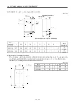
Table 14.1 Recommended wires
Wires [mm
2
]
Servo amplifier
1)
L
1
L
2
L
3
2) L
11
L
21
3)
U V W
4) P C 5)
B1 B2
6)
BU BV BW
7)
OHS1 OHS2
MR-J3-10T (1)
MR-J3-20T (1)
MR-J3-40T (1)
MR-J3-60T
MR-J3-70T
1.25 (AWG16)
MR-J3-100T
2 (AWG14)
2 (AWG14)
MR-J3-200T
3.5 (AWG12)
3.5 (AWG12)
MR-J3-350T
5.5 (AWG10)
5.5 (AWG10)
MR-J3-500T 5.5(AWG10):
b(note)
5.5(AWG10):
b(note)
2(AWG14)
MR-J3-700T 8(AWG8):
c(note)
8(AWG8):
c(note)
3.5(AWG12): b
MR-J3-11KT
(Note2)
14(AWG6): c
22(AWG4): d
MR-J3-15KT
(Note2)
22(AWG4): d
30(AWG2): e
MR-J3-22KT
(Note2)
50(AWG1/0): f
1.25
(AWG16)
60(AWG2/0): f
5.5(AWG10): a
1.25 (AWG16)
2(AWG14) 1.25(AWG16)
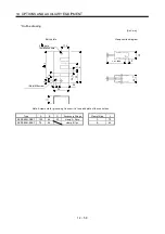
Note 1. For crimping terminals and applicable tools, refer to Table 14.2.
2. When connecting to the terminal block, be sure to use the screws which are provided with the terminal block.
Summary of Contents for MELSERVO MR-J3-xT
Page 22: ...8 MEMO ...
Page 156: ...4 46 4 SIGNALS AND WIRING MEMO ...
Page 276: ...7 26 7 MR Configurator MEMO ...
Page 324: ...10 16 10 SPECIAL ADJUSTMENT FUNCTIONS MEMO ...
Page 418: ...14 66 14 OPTIONS AND AUXILIARY EQUIPMENT MEMO ...

