


Chapter
11 T
roubleshooting
11.4 Alarm Codes of Driver Unit
11-75
ME0392-4C
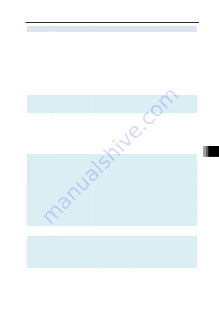
Alarm code
Alarm name
Causes/countermeasures
0C0
Excessive actual speed
Cause: Motor rotation speed exceeded the allowable rotation speed.
1) The sliding resistance of the actuator is locally excessive.
2) External force is applied momentarily.
A sudden speed increase may have occurred before
detecting the servo error.
Countermeasure: This does not occur in normal operation, so confirm
that there are no assembly errors. Also, confirm
whether external force is applied in the direction of
travel.
0C1
Servo error
Cause: 2 or more seconds have passed without being able to move
after receiving the travel command.
1) Connection failure or disconnection of the actuator connecting cable.
2) The brake cannot be released (for models with brake).
3) The load on the motor is large due to external force.
4) The sliding resistance of the actuator is excessive.
Countermeasure: 1) Check the wiring status of the actuator
connecting cable.
2) If there is no problem with the 24V DC power
supplied to the control power connector of the
gateway unit, the RSEL system may be faulty.
Contact IAI.
3) Confirm that there are no assembly errors in
machine components.
4) If the load weight is within the specifications, turn OFF the
power supply and manually check the sliding resistance.
0C2
S
Driver limited
Overrun sensor detected
Cause: This indicates that a signal from the OT sensor (option)
installed at the mechanical end is detected.
1) The actuator was moved by hand or received external force
while the servo was OFF (normal detection).
2) A jog operation was made under a condition that the home
coordinates are not established and the soft stroke limit
would not work properly.
3) The home position achieved by home return is not correct,
or in the case of an absolute type controller the coordinates
have shifted due to an inappropriate absolute reset
position.
4) There is a mismatch between the sensor characteristics
and the setting in Parameter No.19 “Overrun sensor input
polarity”, or the wiring layout is wrong.
5) There is a mistake in the combination of the controller and
actuators, or the setting in Parameter No. 3 and 4 “Soft
Limit” or Parameter No. 77 “Ball Screw Lead Length” is
inappropriate.
Countermeasure: If 1) or 2) is suspected, move the actuator in the
opposite direction by hand.
If this error occurred inside the effective stroke
range, 3), 4), or 5) is a likely cause.
If 3) is suspected, check the home position. Conduct
the absolute reset again if it is the absolute type.
If 4) or 5) is suspected, please contact IAI.
0C5
A
Driver limited
Unauthorized control
system transition
command
Cause: 1) Operation was switched to normal position control operation
during “damping control” operation.
2) Operation was switched to “damping control” operation
during normal position control operation.
Countermeasure: For both 1) and 2), change the sequence so that the
next operation is performed after confirming that
positioning complete signal PEND is ON.
11.4 Alarm Codes of Driver Unit
ME0392-4C
11-76
Alarm code
Alarm name
Causes/countermeasures
0CE
Control power supply
voltage drop
Cause: Gateway unit control power supply voltage has dropped to or
below 16.8V (70% of 24V DC).
1) Control power supply voltage drop
2) 24V DC power supply capacity is insufficient
3) The power supply voltage has dropped.
4) Malfunction of parts inside the RSEL system
Countermeasure: 1) Confirm that voltage of 24V DC ±10% is being
applied to the gateway unit control power
connector. If the voltage is low, the 24V DC
power supply may have failed.
2) Insufficient power capacity for actuator drive. Confirm
the required power capacity in the instruction manual
and replace the 24 VDC power supply.
3) 4) Contact IAI.
0D2
A, D
Driver limited
Excessive motor power
supply voltage
Cause: There is a possibility of component failure inside the RSEL
system.
Countermeasure: If it occurs frequently, the probability of RSEL
system failure is high. Contact IAI.
0D6
Fan error detection
Cause: 1) The number of revolution of the fan in the fan unit mounted
on the driver unit has dropped by 50%.
2) The number of revolution of the fan unit mounted on the
200V system power supply unit has dropped by 50%. (When
detail code is 0001H in the alarm list in the teaching tool)
Countermeasure: 1) 2) Replace the fan unit.
Refer to [12.3.2 How to Replace Fan Unit] and
[12.3.3 How to Replace Fan Unit for 200V Driver
Unit (page 12-8)] for how to make replacement.
0D8
Deviation overflow
Cause: The position deviation counter overflowed.
1) The unit decelerated or stopped due to the influence of
external force or overload during travel.
2) The excitation detection operation after power ON is
unstable.
3) The power supply voltage has dropped.
4) The servo gain number is too low.
Countermeasure: 1) This occurs when the actuator cannot operate
according to commands. Check the load
condition, such as whether the workpiece is
interfering with surrounding objects, whether the
brake is released, etc., and resolve the cause.
2) There may be an overload, so review the payload
and start home return again.
3) Check power supply voltage.
4) Adjust the servo gain number.
0D9
Software stroke limit over
error
Cause: The present position of the actuator exceeds the software stroke limit
Countermeasure: Return to the software stroke limit range.
0DC
Push-motion operation
range exceeded error
Cause: 1) The push-back force was too strong after pushing was completed,
pushing back to the push-motion start setting position.
2) The workpiece was pushed during the approach operation
before shifting to push-motion.
Countermeasures: 1) Re-set and reduce the push-back force.
2) Correct the push-motion start setting position to
the front and shorten the approach distance.
0ED
P, A
Driver limited
Absolute encoder error
detection 1
Cause: The present position changed while reading or saving absolute
data.
Countermeasures: Do not apply vibration to the actuator.
Summary of Contents for R-unit RSEL
Page 2: ......
Page 5: ...ME0392 4C 2 Quick Start Guide Japanese Only ...
Page 32: ...Actuator Coordinate System Intro 18 ME0392 4C 2 Slider type 3 Table type 0 0 0 0 ...
Page 50: ...Chapter 1 RSEL System 1 4 Installation 1 13 ME0392 4C ...
Page 244: ...Chapter 4 Unit connection Installation and Wiring 4 5 PIO Circuit 4 32 ME0392 4C ...
Page 316: ...Chapter 5 Operation 5 10 ELECYLINDER Operation 5 52 ME0392 4C ...
Page 438: ...Chapter 6 Field Network PIO SIO 6 5 Example of Connectivity Setting 6 120 ME0392 4C ...
Page 532: ...10 6 Servo Gain Adjustment 10 90 10 7 Parameter Configuration Advanced Use 10 93 ...
Page 638: ...Chapter 10 Parameter 10 7 Parameter Configuration Advanced Use 10 106 ME0392 4C ...
Page 838: ...Chapter 14 Warranty 14 Warranty 14 3 ME0392 4C ...
Page 843: ......
Page 844: ......