


Chapter 3 Specifications for each unit
3.6
EC Connection Unit
3-104
ME0392-4C
(2) How to read the model nameplate
Mark
Explanation of Mark
Use IAI specified cables only.
[Nameplate Location]
↑
Serial number
Model number→
Serial number
→
Caution Mark
Type
→
3.6
EC Connection Unit
ME0392-4C
3-105
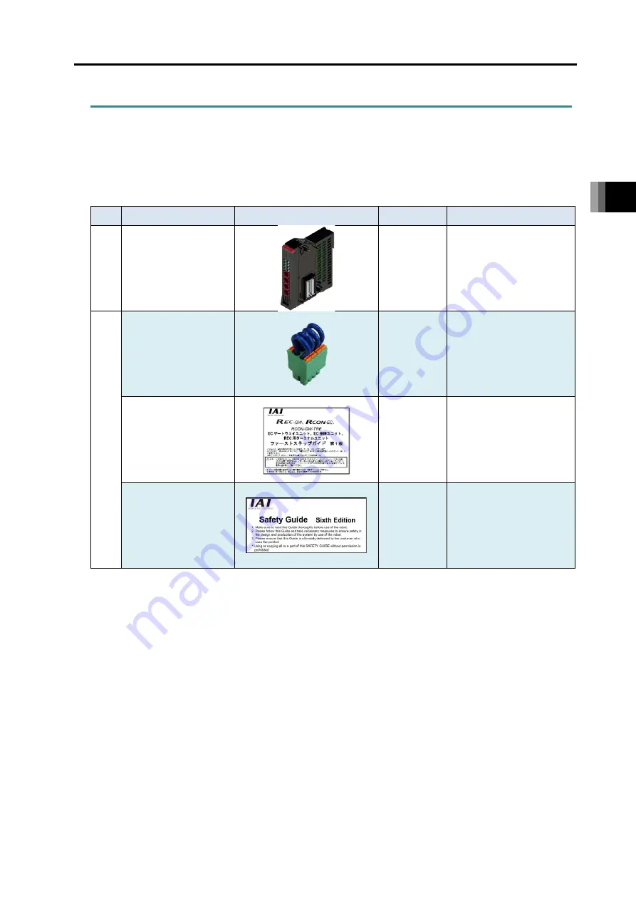
3.6.3 Components
The following table shows the product configuration for the standard specification.
See the packing list for the details of the enclosed components. In the unlikely case that any
model number errors or missing parts come to light, contact your local IAI distributor.
Part name
Shape
Quantity
Remarks
Body
EC Connection Unit
1
Model example: RCON-
EC
Acce
sso
ry
Drive ource shutoff
connector
1
Model:
DFMC1.5/4-ST-3.5
*Supplied with EC
Connection Unit
First Step Guide
1
ME0395
Safety Guide
1
M0194
Summary of Contents for R-unit RSEL
Page 2: ......
Page 5: ...ME0392 4C 2 Quick Start Guide Japanese Only ...
Page 32: ...Actuator Coordinate System Intro 18 ME0392 4C 2 Slider type 3 Table type 0 0 0 0 ...
Page 50: ...Chapter 1 RSEL System 1 4 Installation 1 13 ME0392 4C ...
Page 244: ...Chapter 4 Unit connection Installation and Wiring 4 5 PIO Circuit 4 32 ME0392 4C ...
Page 316: ...Chapter 5 Operation 5 10 ELECYLINDER Operation 5 52 ME0392 4C ...
Page 438: ...Chapter 6 Field Network PIO SIO 6 5 Example of Connectivity Setting 6 120 ME0392 4C ...
Page 532: ...10 6 Servo Gain Adjustment 10 90 10 7 Parameter Configuration Advanced Use 10 93 ...
Page 638: ...Chapter 10 Parameter 10 7 Parameter Configuration Advanced Use 10 106 ME0392 4C ...
Page 838: ...Chapter 14 Warranty 14 Warranty 14 3 ME0392 4C ...
Page 843: ......
Page 844: ......