


Precautions for Handling
Intro-10
ME0392-4C
8. PIO Signal Sending and Receiving
Pay attention to the followings when sending and receiving PIO signals.
If exchanging data between devices with different scan time, the length of time required for a
reliable signal reading process is greater than the longer scan time. (In order to safely perform
the reading process on the PLC side, we recommend using a timer set value of at least twice
the longer scan time.)
●
Operational image
As shown in the diagram, if exchanging data
between 2 devices with different scan time,
obviously the I/O timing will not match.
When the signal of this controller turns ON, there
is no guarantee that the PLC will read it
immediately.
In cases like this, in order to achieve reliable
reading, set the PLC side to read after a period
greater than the longer scan time has passed.
This also applies when the reading is performed
on the controller side.
On this occasion, make sure the safety factor of
the timer setting is 2 to 4 times or more of the
scan time.
As the timer is also processed within the scanning
process, setting below the scan time is
dangerous.
The example shown in the diagram indicates that
even if this controller performs output process
once every 1 ms, the PLC can only recognize
once every 20 ms.
The PLC only performs the output process once
every 20 ms, meaning that it keeps recognizing
the same output status for that period.
Also, if reading is performed while the other device is rewriting output, incorrect signals may be read
at times. Wait until the rewriting is completely finished (allow interval of 2 scans or more), then
perform reading. In terms of the output-side device, do not allow its output to change until the other
device finishes the reading. Additionally, an input constant is set for the input component to prevent
mistaken detection of noise, etc. so it only accepts signals that last more than a certain period of
time. It is necessary to add this period of time as well.
This controller
(Scan time 1 ms)
PLC
(For example, scan time 20 ms)
Output
Process
Input
Process
Precautions for Handling
ME0392-4C
Intro-11
9. PLC timer setting
The PLC timer setting should not be at minimum set value.
If "1" is set, some PLCs turn ON somewhere between 0 and 100 ms with a 100 ms timer, or
between 0 and 10 ms with a 10 ms timer.
Consequently, the process which will be performed is the same as when a timer is not set, which
may lead to failures such as failing to position to a specified position No. in positioner mode, etc.
The minimum set value of the 10 ms timer should be "2", and when required to set to 100 ms,
use the 10 ms timer and set it to "10".
10. Battery-less absolute specification actuators
(1) For stepper motor specification, driver unit parameter setting allows switching between
absolute specification and incremental specification.
• Driver unit parameter No.83 "Absolute Unit"
0: Not in use (incremental specification), 1: In use (absolute specification)
(2) RCP5 series actuators will perform slight position adjustment operation due to characteristics
of the stepper motor during initial servo ON only, after the power is turned ON.
Maximum travel during position adjustment operation is 0.025 x lead length [mm].
Additionally, until servo turns ON, the present position displayed on the teaching tool will be
the coordinates prior to the adjustment operation.
(3) After the power is turned ON followed by the initial servo ON, home return complete signal
will be output.
(4) If the initial servo ON is executed outside range of the software limit, no error will be output.
After traveling within the range, monitoring of the software limit will start.
(5) If the motor unit is removed from the actuator for motor replacement, etc., be sure to perform
home return motion (absolute reset).
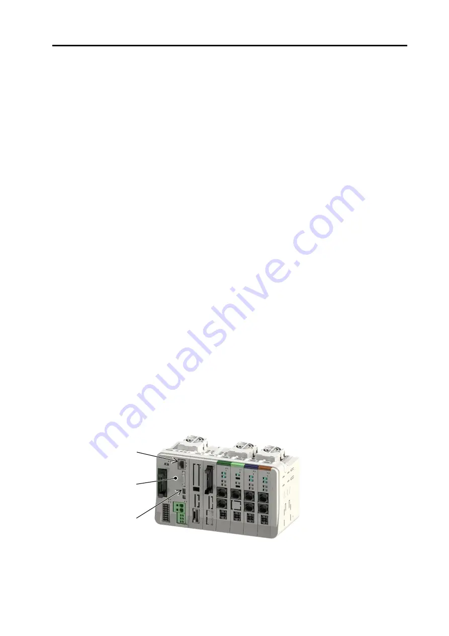
11. External communication connector
The SEL unit has 3 types of communication connector (refer to 4.8 to 4.10).
• Teaching connector
• USB connector (USB mini-B connector)
• Ethernet connector
Do not connect multiple connector and perform communication simultaneously.
This may result in following errors:
• Occurrence of communication error
• Occurrence of unpredictable operation
Ethernet Port
SIO Port
USB Port
Summary of Contents for R-unit RSEL
Page 2: ......
Page 5: ...ME0392 4C 2 Quick Start Guide Japanese Only ...
Page 32: ...Actuator Coordinate System Intro 18 ME0392 4C 2 Slider type 3 Table type 0 0 0 0 ...
Page 50: ...Chapter 1 RSEL System 1 4 Installation 1 13 ME0392 4C ...
Page 244: ...Chapter 4 Unit connection Installation and Wiring 4 5 PIO Circuit 4 32 ME0392 4C ...
Page 316: ...Chapter 5 Operation 5 10 ELECYLINDER Operation 5 52 ME0392 4C ...
Page 438: ...Chapter 6 Field Network PIO SIO 6 5 Example of Connectivity Setting 6 120 ME0392 4C ...
Page 532: ...10 6 Servo Gain Adjustment 10 90 10 7 Parameter Configuration Advanced Use 10 93 ...
Page 638: ...Chapter 10 Parameter 10 7 Parameter Configuration Advanced Use 10 106 ME0392 4C ...
Page 838: ...Chapter 14 Warranty 14 Warranty 14 3 ME0392 4C ...
Page 843: ......
Page 844: ......