


Chapter
11 T
roubleshooting
11.3 Error List
11-67
ME0392-4C
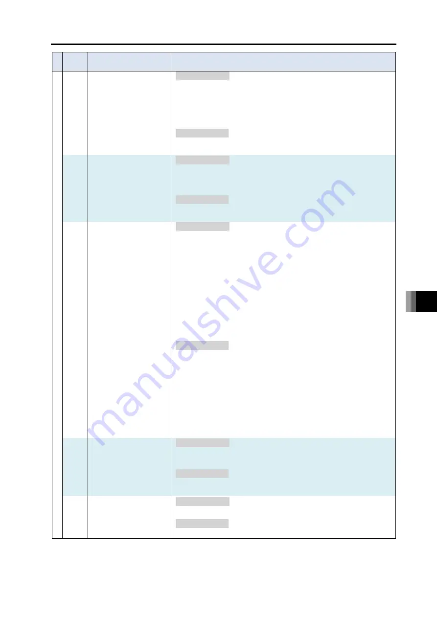
Error
No.
Error name
Content and Cause /
Countermeasure
Co
ld
-st
art
63A
Axis Feature Definition
Parameter Error
[Content & Cause]
There is an error in the parameter setting related to the combination unit
(such as wrist unit)
1) There is an error in a value set in the unit type (such as wrist unit) or
unit axis indication (such as B and T-axes)
2) There is an error in a value set in the unit number (from 0 to 4)
3) An item not supported by the unit such as the axis operation type,
encoder type and home-return system is set
4) An item not supported by the unit such as synchronizing and multiple
slider is set
[Countermeasure]
1), 3) Change the value to an appropriate in the parameters in the driver unit
2), 4) Establish the settings again in the configuration tool.
If the configuration tool is not used, change the values appropriately
in the following parameters
• Axis Parameter No. 15 (Combination Unit Number)
• Axis Parameter No.16 (Synchronizing Combination Number)
• Axis Parameter No.41 (Multiple Slider Excess Approach
Detection Target Axis Indication)
63B
Coordinate system
definition setting error
[Content & Cause]
It is a combination of actuators not to use the coordinate system features
[Countermeasure]
Set it to 0 (No Orthogonal Coordinates) in Axes Group Parameter No. 10
63C
Axis construction
parameter error
[Content & Cause]
An error was detected in a parameter (Axes Group Parameter No. 1 to 8)
related to the axis construction
1) Connection of the driver unit axis indicated was not detected
2) A value set in the parameter is out of the range
3) The number of axes to be used exceeded the upper limit (8)
4) An axis was indicated duplicated
[Countermeasure]
1) When an error related to the communication with the driver unit (such
as 621 and 63E) is generated at the same time take a countermeasure
to each error. If the driver unit was taken off, conduct the configuration
again.
2), 3), 4) Conduct the configuration again and set the correct parameters
63D
Unit linkage error
[Content & Cause]
There is a concern that each unit is not linked correctly to each other.
1) A coupling connector or a SCON
connection connector is not properly
joined
2) There is a line breakage on an internal signal line or an SCON
connection cable
3) There is no terminal unit or terminal connection connector (for SCON)
installed
[Countermeasure]
1), 2) Confirm that each unit is linked together firmly with each other.
Disconnect the link between each unit once and reconnect the link
again. If the error occurs again even after the power reboot, contact IAI.
3) Install a terminal unit or terminal connector
63E
Number of driver axes
error
[Content & Cause]
1) Driver units are connected for nine axes or more
[Countermeasure]
1) Have the driver units connected for eight axes or less
11.3 Error List
ME0392-4C
11-68
Error
No.
Error name
Content and Cause /
Countermeasure
Co
ld
-st
art
640
Data Output Parameter
Error
[Content & Cause]
There is an error described below in the data output related parameter
settings
1) There is an error in a parameter
2) The axis data output port is duplicated
3) The system output port is duplicated
[Countermeasure]
1), 2), 3) Establish the output data setting again in the IO output setting
window.
641
Parameter mismatch
error
[Content & Cause]
There are parameters with the settings mismatched
1) The settings in Driver Unit Parameter No. 5 “Home-Return Direction”
and No. 62 “Pulse Count Direction” are different
[Countermeasure]
1) In case the home-return direction has been changed, change the pulse
count direction setting at the same time.
642
Option unit
communication error
[Content & Cause]
There is a communication error occurred in the communication with an
option unit (unit other than driver unit or power supply unit).
1) Connectors are not joined properly
2) There is a breakage on a signal line inside
3) Communication error due to influence of noise
4) There is no terminal unit installed
5) Nine units or more option units are connected
6) There is an error in an option unit related parameter
7) The connected option unit differs from what is set in the parameter.
8) The total of the number of driver axes and EC axes exceeds 16 axes.
9) There was an error occurred in communication between the EC
connection unit and the EC.
[Countermeasure]
1) to 3) Confirm that each unit is linked together firmly with each other.
Disconnect the link between each unit once and reconnect the
link again. If the error occurs again even after the power reboot,
contact IAI.
4) Install a terminal unit.
5) Have the connected option units for 8 units or less.
6) Check in I/O Parameter No. 186 to 190
7) Align the option unit and the setting in Option Board Parameter No. 1.
8) Arrange the number of driver or EC axes to be 16 axes or less.
9) Check the connectivity of the cable on the EC connection unit.
643
Emergency-stop, enable
switch recovery type
parameter error
[Content & Cause]
An emergency stop or enable switch recovery type not available in the
robot currently connect is set
[Countermeasure]
Set a value other than “2: Operation Continuous Recovery” to Other
Parameter No. 10 and 11.
644
EMG logic error
[Content & Cause]
1) Malfunction on SEL unit
[Countermeasure]
1) Replace SEL unit
Summary of Contents for R-unit RSEL
Page 2: ......
Page 5: ...ME0392 4C 2 Quick Start Guide Japanese Only ...
Page 32: ...Actuator Coordinate System Intro 18 ME0392 4C 2 Slider type 3 Table type 0 0 0 0 ...
Page 50: ...Chapter 1 RSEL System 1 4 Installation 1 13 ME0392 4C ...
Page 244: ...Chapter 4 Unit connection Installation and Wiring 4 5 PIO Circuit 4 32 ME0392 4C ...
Page 316: ...Chapter 5 Operation 5 10 ELECYLINDER Operation 5 52 ME0392 4C ...
Page 438: ...Chapter 6 Field Network PIO SIO 6 5 Example of Connectivity Setting 6 120 ME0392 4C ...
Page 532: ...10 6 Servo Gain Adjustment 10 90 10 7 Parameter Configuration Advanced Use 10 93 ...
Page 638: ...Chapter 10 Parameter 10 7 Parameter Configuration Advanced Use 10 106 ME0392 4C ...
Page 838: ...Chapter 14 Warranty 14 Warranty 14 3 ME0392 4C ...
Page 843: ......
Page 844: ......