


Chapter 10 Parameter
10.3
Parameter List (Driver Unit)
10-74
ME0392-4C
[BU Velocity Loop Integral Gain (Parameter No. 154)]
No.
Name
Unit
Input range
Default initial value setting
154 BU velocity loop integral
gain
-
1 to 99,999,999
In accordance with actuator
When Parameter No. 152 “High Output Setting” is enabled and Parameter No. 144 “GS
Magnification Upper Limit” is set to 100 or less, the setting of this parameter is enabled for
Velocity Loop Integral Gain.
For details, refer to Parameter No. 32 “Velocity Loop Integral Gain (page 10-60”.
For the conditions for using this item, refer to [Selection and use of Velocity Loop Proportional
Gain and Velocity Loop Integral Gain] on the bottom of page 10-60.
[ABS Battery Retaining Time (Parameter No. 155)]
No.
Name
Unit
Input range
Default initial value setting
155 ABS battery retaining time
-
0: 20 days
1: 15 days
2: 10 days
3: 5 days
0
This function is limited to the simple absolute specification. Set encoder positional data retention
time after turning the power supply to the actuator OFF. The setting is available in 4 levels. The
lower the motor rotation speed setting is, the longer the retention time of the positional data can
be. If there is a possibility of external force moving the workpiece conveying components of the
actuator such as the slider or rod while power is OFF, refer to the following table and calculate
motor revolution based on movement speed and set the value of this parameter faster. If the
motor revolution exceeds the set value, positional data will be lost.
The motor rotation speed can be calculated with the equation below.
Motor revolution [r/min] = Movement speed [mm/s] / Actuator lead [mm] x 60 [s/min]
For details, refer to [3.7.4 General Specifications (page 3-119)].
Parameter
No.155
settings
Upper limit of encoder rotation speed when
power is OFF [r/min]
Battery
retaining
time
guideline
[days]
Retaining time
per 1 hour of
charge time
(guideline)
[h]
If connected actuator
is not RCA2-***NA
If connected actuator
is RCA2-***NA
0
100
75
20
6.6
1
200
150
15
5.0
2
400
300
10
3.3
3
800
600
5
1.6
24V AC servo motor specification and
stepper motor specification only
Stepper motor specification only
10.3 Parameter List (Driver Unit)
ME0392-4C
10-75
[Enabled/Disabled Axis Select (Parameter No. 158)]
No.
Name
Unit
Input range
Default initial value
setting
158 Enabled/disabled axis
select
-
0: Enabled
1: Disabled
0
Set this parameter disabled when an operation is required with number of axes less than that of
purchased.
A disabled axis is not available to select in “RSEL Axis Setting”.
Disabling an axis after the RSEL axis setting is established should require establishment of the
RSEL axis setting again.
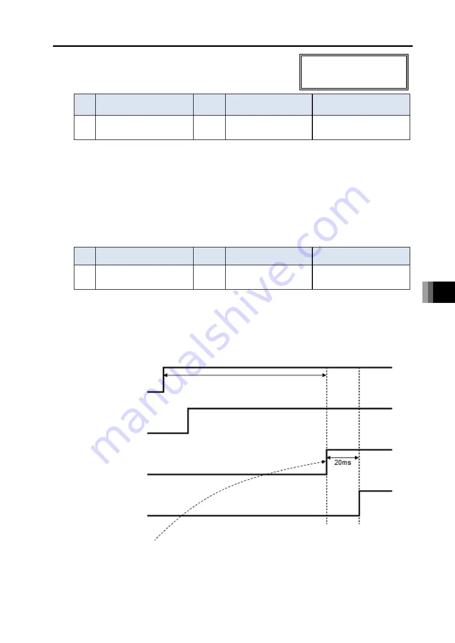
[Delay Time after Shutdown Release (Parameter No. 165)]
No.
Name
Unit
Input range
Default initial value setting
165 Delay Time after
Shutdown Release
ms
0 to 10,000
0
The setting should be established for the duration till it gets available to have the servo on when
it takes time for the rising of the cutoff source due to such a reason as the external drive cutoff
circuit at the cancellation of the emergency stop. There is no need of making a change when
having a drive cutoff only on an internal drive cutoff relay in a controller.
24V AC servo motor specification,
DC brush-less motor specification
and Stepper motor specification only
Shutdown
・
Emergency Stop
・
Enable Switch etc.
RSEL Servo-ON
command
Driver Servo-ON
command reception
Servo-ON complete
If the on-edge 2) of external servo-ON command came after the point of passing SDDT
time 1), the condition becomes reception of controller internal servo-ON command at
the point of 2).
1)
2)
Summary of Contents for R-unit RSEL
Page 2: ......
Page 5: ...ME0392 4C 2 Quick Start Guide Japanese Only ...
Page 32: ...Actuator Coordinate System Intro 18 ME0392 4C 2 Slider type 3 Table type 0 0 0 0 ...
Page 50: ...Chapter 1 RSEL System 1 4 Installation 1 13 ME0392 4C ...
Page 244: ...Chapter 4 Unit connection Installation and Wiring 4 5 PIO Circuit 4 32 ME0392 4C ...
Page 316: ...Chapter 5 Operation 5 10 ELECYLINDER Operation 5 52 ME0392 4C ...
Page 438: ...Chapter 6 Field Network PIO SIO 6 5 Example of Connectivity Setting 6 120 ME0392 4C ...
Page 532: ...10 6 Servo Gain Adjustment 10 90 10 7 Parameter Configuration Advanced Use 10 93 ...
Page 638: ...Chapter 10 Parameter 10 7 Parameter Configuration Advanced Use 10 106 ME0392 4C ...
Page 838: ...Chapter 14 Warranty 14 Warranty 14 3 ME0392 4C ...
Page 843: ......
Page 844: ......