background image


GBC StreamWire 

7/23/2020 

Repairs/Adjustments 


4-183 


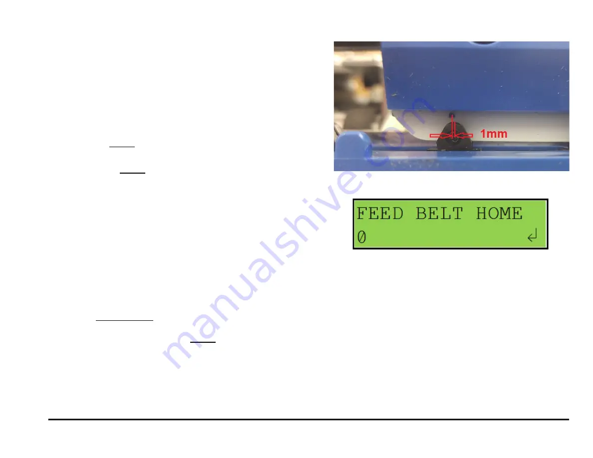
ADJ 1.4   Element Feed Belt Home Position 

To properly feed an element, the belt tooth must enter/mesh with the 

element at the proper position. The Feed Belt Home setting controls 

the point where the belt meshes with the wire openings. 

Inspection Procedure  


1)  Open the element feeder and cheat the safety interlock.  
2)  Enter the service menu of the eWire LCD. 
3)  Navigate through the menus as follows:  

a)

  Service Settings Menu 

 Feed Home Belt


b)  Press the 

ENTER

 button twice to home the belt. 

4)  Check the stop position of the belt tooth.  

a)  If necessary, 

ENTER

 can be pressed 2X again to check the belt 

position repeatedly. 

5)  The belt tooth should be slightly off center from the alignment hole. 

The tooth position should be about 1 mm in front of the hole as 

shown.  

6)  To confirm the mesh is correct, run a feed element per Section 6.3.4 

Feed Element and carefully watch the belt tooth where it engages 

with the wire. The tooth should slide easily into the gap of the wire. If 

the tooth pushes against the wire, it is likely not set to the correct 

position.  

Adjustment Procedure, Fine (for minor adjustments) 

(Recommended): 

1)  Open the element feeder and cheat the safety interlock.  
2)  Do GP 6.3.13 to access the Feed Belt Home adjustment menu (Fig 2) 
3)  Using the 

up/down arrows

, change the value to change the belt 

home position value.  

4)  After making an adjustment, press the 

ENTER

 button twice to cause 

the belt to home. Check the belt tooth location relative to the 

alignment hole. It should be approximately 1 mm in front.  

5)  If the tooth position looks correct relative to the alignment hole, verify 

the setting by watching the element tooth engage with the wire as 

described in the Inspection Procedure. If the belt tooth doesn’t 

engage easily, adjust the Feed Belt Home value until it does.  


Fig 2 

Fig 1 

Summary of Contents for StreamWire

Page 1: ...GBC StreamWire 07 23 2020 Service Manual GBC StreamWire Service Manual Part Number 7716519 Revision Number E1 Issue Date July 2020...

Page 2: ...and clear any scraps debris Save the system settings to a data file Download a log file to USB Note any error codes especially if they occur repeatedly SYSTEM CHECKS Purpose Direct repair activity fo...

Page 3: ...ich arise directly or indirectly from such service Changes are periodically made to this document Changes technical inaccuracies and typographic errors will be corrected in subsequent editions Copyrig...

Page 4: ...tion Contents Title Page Table of Contents iii Introduction iv Organization v How to Use This Documentation v Other Information vi The Use of Caution Warning and Note statements vi Safety Devices vii...

Page 5: ...l Action The maintenance and diagnostic activities in this section may direct the Service Representative to perform additional service activities found elsewhere in the documentation such as RTPs Repl...

Page 6: ...se of Caution Warning and Note statements Information relative to the completion of a task in a safe or thorough manner will be supplied in the form of a Caution a Warning or a Note statement These st...

Page 7: ...ve all ESD procedures to avoid component damage Operational Safety Do not operate the GBC eWire with the interlocks defeated Use care when a procedure in this Manual instructs you to insert an Interlo...

Page 8: ...e proper grounding type power outlet If you are unable to insert the plug into an outlet contact a qualified electrician to have a suitable outlet installed Do not alter the plug on the end of the cor...

Page 9: ...GBC StreamWire 07 23 2020 Service Manual ix Notes...

Page 10: ...1 Service Call Procedures Section Contents Title Page CALL FLOW 1 2 INITIAL ACTION 1 3 SYSTEM CHECKS 1 3 EVERY CALL ACTIVITIES 1 4 SCHEDULED MAINTENANCE 1 4 eWIRE MAINTENANCE SCHEDULE 1 5 Periodic Mai...

Page 11: ...o suggest a direction for using the information obtained during Initial Action You can then repair and verify the effectiveness of the repair This step may also provide information to assist in the id...

Page 12: ...a data file Download a log file to USB Note any error codes especially if they occur repeatedly SYSTEM CHECKS Purpose Direct repair activity for problems found in Initial Action PROCEDURE Select the...

Page 13: ...Cleaning Perform GP 6 12 Internal Cleaning Perform GP 6 13 Base Cleaning Perform GP 6 15 Optical Sensor Cleaning SCHEDULED MAINTENANCE PROCEDURE Check the number of Bind Cycles and Sheet Cycles in the...

Page 14: ...nt at Stack Position 1M sheets Inspect Perform ADJ 1 10 Book Drawer Belt 1M sheets Inspect See GP 6 17 Kick Downs 1M sheets Inspect See GP 6 10 Paper Path and Other Sensors 1M Sheets Inspect Clean Ant...

Page 15: ...red Install close all covers and doors Run the eWire using the same settings as the customer was using when the problem occurred If necessary run a variety of different paper and spool size configurat...

Page 16: ...E DETECT TIMEOUT 2 28 RTP 4 3 J322 S22 ELEMENT AT PYRAMID TIMEOUT 2 29 RTP 4 4 J323 S23 KNIFE HOME TIMEOUT 2 30 RTP 4 5 J324 S24 PUSHOVER HOME TIMEOUT 2 30 RTP 4 6 J325 S25 FEED BELT HOME TIMEOUT 2 31...

Page 17: ...HOME TIMEOUT 2 59 RTP 5 20 J390 HOLDER ROTATE HORIZONTAL TIMEOUT 2 60 RTP 5 21 J391 HOLDER ROTATE VERTICAL TIMEOUT 2 62 RTP 5 22 J392 HOLDER STACK POSITION STEPS TIMEOUT 2 64 RTP 5 23 J393 HOLDER WAI...

Page 18: ...there is there an operator message There is an operator message on line 1 Y N Go to Step 4 Go to the Table of Contents for Section 2 and locate the RTP for that status message 4 Check the top row of...

Page 19: ...ray CLOSE TRAY The Book tray is pulled out Insert the Book tray READY The eWire is ready for Operation n a b Bottom Row of Text Message Description Action ADD ELEMENTS Element spool is almost empty no...

Page 20: ...heck Sensor 42 Sensor 43 Sensor 45 Book drawer Full Remove any debris or obstructions This clears the fault code Y N Go to step 5 Normal operation 5 Do GP 6 5 10 to check Motor 19 Drawer elevation mot...

Page 21: ...he A Main Control Board Interlock Cable is connected at J18 Y N Make the connection and return to normal operation 6 Switch OFF the machine and unplug the Power Cord 7 Remove the M4 screws that hold t...

Page 22: ...f Close Door This message is displayed when the Door for the element feeder module is left open or not properly closed 1 Open the door pull out the Element drawer and reinsert firmly This clears the f...

Page 23: ...ly This clears the fault Y N Go to Step 2 Return to normal operation 2 Insert an Interlock Cheater into the Top cover interlock Switch WARNING Moving Parts keep hands clear of nips and the belts when...

Page 24: ...ock Switch Replacement to replace the Interlock switch Replacing the switch clears the fault Y N Go to Step 9 Return to normal operation 9 Replace Interlock Switch Cable 7716716 Replacing the cable cl...

Page 25: ...displays the area of the machine where the error occurred a Fault Code Text Each Fault code starts with the letter J followed by a 3 digit code b Fault Code Areas Fault Code areas are identified in t...

Page 26: ...m Paper transport module Entrance and Exit Extension Do RTP 3 x Jam 2xx Paper transport jam Paper transport module Do RTP 3 x Jam 32x Jam 33x Jam 35x Jam 36x Wire jam Element feeder module Do RTP 4 x...

Page 27: ...ted at S4 1 J105 First sheet located at S5 1 J106 First sheet located at S6 1 3 3 1 J107 First sheet located at S7 1 3 3 1 J108 First sheet located at S8 1 3 3 1 J109 First sheet located at S9 1 3 3 1...

Page 28: ...page 7 2 is connected to the ground and to the AC Filter Ground Wire is connected Y N Connect Ground Wire Go to step 8 8 Check that Cable 7716727 See Section 7 page 7 2 is connected at the AC Filter...

Page 29: ...2020 RTPS 2 14 15 Check for output voltage 24 VDC on Cable 7716726 at the 24 VDC power supply There is DC power on Cable 7716726 at the Power Supply Y N Replace the 24 VDC power supply REP 11 4 Go to...

Page 30: ...en color When the polarity of 24V DC wires is correct Polarity of the wires is not correct B Main control board LED description ON OFF 24V When there is 24V DC power supply to the board When there is...

Page 31: ...ol Board Y N Go to Step 10 Replace 24V DC power supply REP 11 3 10 Replace Cable 7716726 This clears the fault Y N Go to Step 11 Return to normal operation 11 Check if there is 24V power to any other...

Page 32: ...k the LEDs on the Control Board With the cover door drawer closed there will be 5 LEDs that will be lit on the AC board and 5 LEDs lit on the B board With the cover door drawer open there will be 4 LE...

Page 33: ...LCD Cable 7716713 is connected at the LCD Panel on the rear of the User Interface See Section 7 page 7 2 and PL 2 2 Cable 7716713 is connected at the LCD Panel Y N Connect Cable 7716713 5 Upload firmw...

Page 34: ...Y N Connect the Cable Do REP 1 10 LCD Membrane switch replacement RTP 2 6 Close Door Tray Cover Message When All Are Closed Use this RTP when the message CLOSE DOOR CLOSE TRAY or CLOSE COVER is displ...

Page 35: ...entry sensor 1 but not detected by the skew sensor S6 S10 1 Perform GP 6 4 2 Sensor check of S6 S10 This clears the fault Yes Return to normal operation No Go to step 2 2 Ensure that the eWire is pro...

Page 36: ...e the appropriate RTP Location of the first jammed sheet is before the Steering module rollers N4 N5 Go to RTP 3 3 1 Location of the first jammed sheet is before the Diverter gate Go to RTP 3 3 2 Loca...

Page 37: ...s are not disengaged when L2 and L3 are not actuated Yes Go to Step 5 No If N1 does not engage and disengage replace L2 REP 2 19 If N2 does not engage and disengage replace L3 REP 2 19 5 Inspect rolle...

Page 38: ...ep 5 5 Do GP 6 6 to inspect solenoids L2 L3 and L4 This clears the fault Yes Return to normal operation No Go to Step 6 6 Inspect rollers N1 N2 N3 N4 and N5 GP 6 14 This clears the fault Yes Return to...

Page 39: ...is clears the fault Yes Return to normal operation No Go to Step 4 4 Do GP 6 6 to inspect solenoids L2 L3 and L4 This clears the fault Yes Return to normal operation No Go to Step 5 5 Inspect rollers...

Page 40: ...s clears the fault Yes Return to normal operation No Go to Step 5 5 Inspect rollers N8 N1 N2 N3 N4 N5 and N6 GP 6 14 This clears the fault Yes Return to normal operation No Go to Step 6 6 Inspect the...

Page 41: ...17 M18 and M1 This clears the fault Yes Return to normal operation No Go to Step 5 5 Do GP 6 6 to inspect solenoids L5 L6 L7 L2 L3 and L4 This clears the fault Yes Return to normal operation No Go to...

Page 42: ...to step 4 4 Perform GP 6 7 and GP 6 8 to reinstall the Supply Spool Replacing the spool with a new one fixes the problem Yes Reinstall the correct size spool and continue operation No Go to Step 5 5 D...

Page 43: ...6 3 6 Functional Tests and run the Feed Element function Ensure that the element moves feely on the Element Feed Track with no burrs or obstructions Element moves freely on the Element Feed Track Yes...

Page 44: ...Belt Home sensor This clears the fault Yes Return to normal operation No Go to step 7 7 Check the condition of the Element feed track assembly PL 5 9 Element feed track assembly is in good condition Y...

Page 45: ...out is the maximum time to wait for the Element transfer pushover assembly to reach home 1 Do GP 6 4 to check S24 Pushover Home sensor This clears the fault Yes Return to normal operation No Go to St...

Page 46: ...No Go to step 2 2 Do GP 6 5 to check M10 Element feed belt motor This clears the fault Yes Return to normal operation No Go to step 3 3 Inspect the Element belt PL 5 8 Check for missing teeth or any o...

Page 47: ...s the fault Yes Return to normal operation No Go to Step 2 2 Do GP 6 5 to check M13 Expanding T motor This clears the fault Yes Return to normal operation No Go to step 3 3 Inspect the Expanding T cam...

Page 48: ...Expand T Out timeout is the maximum time to wait for the Expand T to reach its home position 1 Do GP 6 4 to check S33 Expanding T Out sensor This clears the fault Yes Return to normal operation No Go...

Page 49: ...ol Board Replacement This clears the fault Yes Return to normal operation No Escalate to second level RTP 4 9 J334 FEED BELT JAM Feed belt jam is reported when the Element home sensor does not change...

Page 50: ...n element spool with at least one full row of elements 1 Check if the element spool is loaded properly and if it contains at least one row of elements Try loading a fresh spool and repeat the process...

Page 51: ...1 Element detect at Knife and S22 Element detect at Pyramid Follow this procedure when this message is displayed erroneously i e when there is no element present on the belt or if this jam occurs very...

Page 52: ...Go to Step 5 No Go to step 7 5 When doing the Feed Element test determine if there is a gap between the cut section of wire and the remaining wire If the wire is bunched up this can cause erroneous J...

Page 53: ...spool is loaded properly Yes Go to Step 5 No Remove the element spool and reinsert it properly 5 Inspect the Element belt PL 5 8 Check for missing teeth or any other damages Element belt is in good co...

Page 54: ...the damaged element and reinstall the spool 2 Check if the element spool is loaded properly Element spool is loaded properly Yes Go to Step 3 No Remove the element spool and reinsert it properly 3 Man...

Page 55: ...the element to mesh with the Element belt 1 Ensure that the element is not tangled on the sprocket of the feed section The Element is not tangled on the sprocket Yes Go to Step 2 No Untangle the eleme...

Page 56: ...o RTP 4 17 J366 ELEMENT AT PUSHOVER STEPS TIMEOUT J366 is triggered if it takes longer than specified time for motor M10 to complete the necessary number of steps from the S22 Element Detect at Pyrami...

Page 57: ...No Go to Step 2 2 Do GP 6 5 to check M12 Element pushover motor This clears the fault Yes Return to normal operation No Go to Step 3 3 Replace the Pushover Motor Assembly PL 5 13 This clears the faul...

Page 58: ...of the Holder linear drive belt Front and Rear PL 5 21 The timing belt is in good condition There are no missing teeth and the belt is not frayed Yes Go to Step 4 No Replace the damaged timing belt RE...

Page 59: ...d level RTP 5 2 J371 S38 HOLDER POSITION ELEMENT TIMEOUT J371 is triggered if it takes longer than specified time for the Holder to reach S38 Holder at Element position sensor 1 Do GP 6 4 to check S38...

Page 60: ...properly Yes Go to Step 7 No Escalate to second level 7 Do GP 6 5 to check M15 Holder linear drive motor This clears the fault Yes Return to normal operation No Go to step 8 8 Inspect the springs for...

Page 61: ...p 3 No Replace the damaged timing belt REP 8 11 8 12 and resume operation 3 Check the tension of the Holder linear drive belt tension Front and Rear ADJ 1 6 The tension of the timing belts is good Yes...

Page 62: ...gates PL 5 21 Holder gates springs are present and not damaged Yes Go to Step 9 No Replace the missing damaged spring 9 Go to RTP 5 20 Step 5 and 6 to ensure the Holder rotate components are in good...

Page 63: ...ension of the Holder linear drive belt tension Front and Rear ADJ 1 6 The tension of the timing belts is good Yes Go to Step 4 No Do ADJ 1 6 to set the belt tension and resume operation 4 Visually che...

Page 64: ...eturn to normal operation No Escalate to second level RTP 5 5 J374 S46 BOOK DROP TIMEOUT J374 is triggered when it takes longer than the specified time for the Closer to reach S46 Closer Home after th...

Page 65: ...e Closer drive mechanism on the Front side of the machine for any loose objects preventing smooth operation Check if there is any debris like paper scraps loose elements etc in this area that may be r...

Page 66: ...5 5 J374 S46 BOOK DROP TIMEOUT RTP 5 7 J376 CLOSER AT HOLDER STEPS TIMEOUT J376 is triggered when it takes longer than the specified time for the Closer to move to the Closer at Holder position from i...

Page 67: ...s housing as shown Cable is plugged in and properly seated Yes Go to Step 3 No Plug in the cable close all covers and cycle the Element Feeder Door interlock This clears the fault Yes Reinstall the Ca...

Page 68: ...RTP 5 11 J381 CLOSER STAGED TIMEOUT J381 is triggered when it takes longer than the specified time for the Closer to reach the S49 Closer Staged Position Do the steps in RTP 5 6 J375 BOOK DROP POSITIO...

Page 69: ...state of S47 Closer Full Open to indicate the Upper Jaw is at its home position Do the steps in RTP 5 10 J380 CLOSER JAWS HOME TIMEOUT RTP 5 14 J384 HOLDER AT CLOSER STEPS TIMEOUT J384 is triggered w...

Page 70: ...and the belt is not frayed Yes Go to Step 3 No Replace the damaged timing belt REP 8 11 8 12 and resume operation 3 Check the tension of the Holder Linear Drive Belt Front and Rear ADJ 1 6 The tension...

Page 71: ...or This clears the fault Yes Return to normal operation No Go to step 8 8 Inspect the springs for the Holder gates PL 5 21 Holder gates springs are present and not damaged Yes Go to Step 9 No Replace...

Page 72: ...Holder Linear Drive Belt Front and Rear ADJ 1 6 The tension of the timing belts is good Yes Go to Step 4 No Do ADJ 1 6 to set the belt tension and resume operation 4 Visually check if the rollers of t...

Page 73: ...FIRMWARE UPGRADE Procedure to Re flash the firmware for eWire This clears the fault Yes Return to normal operation No Go to Step 10 10 Do REP 11 2 B Main Control Board Replacement This clears the fau...

Page 74: ...S40 Holder Near Element Feeder after collecting an element Do the steps in RTP 5 4 J373 S40 AT BOOK DROP POSITION TIMEOUT RTP 5 19 J389 HOLDER PAST HOME TIMEOUT J389 is triggered when a firmware faul...

Page 75: ...on No Go to Step 2 2 Do GP 6 5 to check M14 Holder Rotate This clears the fault Yes Return to normal operation No Go to step 3 3 Check the presence and tightness of the two socket head screws on the H...

Page 76: ...ged components 6 Ensure the linkages are not bent damaged The linkages are not damaged Yes Go to Step 7 No Replace the damaged linkage REP 8 18 7 Do GP 6 3 5 FIRMWARE UPGRADE Procedure to Re flash the...

Page 77: ...o normal operation No Go to Step 2 2 Do GP 6 5 to check M14 Holder Rotate motor This clears the fault Yes Return to normal operation No Go to step 3 3 Check the presence and tightness of the two socke...

Page 78: ...onents 6 Ensure the linkages are not bent damaged The linkages are not damaged Yes Go to Step 7 No Replace the damaged components REP 8 18 7 Do GP 6 3 5 FIRMWARE UPGRADE Procedure to Re flash the firm...

Page 79: ...Stack position after leaving S37 Holder Stack Position Do the steps in RTP 5 1 J370 HOLDER AT S37 TIMEOUT RTP 5 23 J393 HOLDER WAIT VERTICAL TIMEOUT J393 is triggered if it takes longer than the speci...

Page 80: ...value for the Upper Jaw to be at its Partial Closed position for the currently loaded element size Do the steps in RTP 5 26 J396 CLOSER RE HOME ENCODER TIMEOUT RTP 5 25 J395 S28 MOTOR STEPS TIMEOUT J3...

Page 81: ...o normal operation No Go to Step 3 3 Ensure that there are no residual elements or foreign objects in the Closer jaws Closer jaws are free of foreign materials Yes Go to Step 6 No Remove the object s...

Page 82: ...perly tightened Yes Escalate to second level No Tighten the screw to 8 Nm This clears the fault Yes Follow the steps in Section 3 1 Element Closing to achieve proper bind quality then return to normal...

Page 83: ...Pulleys are in good condition Yes Go to Step 3 No Replace the Book Drawer Belt or Pulley 3 Inspect the Book Tray Drive Motor Belt PL 5 24 Ensure that the belt is not frayed or missing any teeth Check...

Page 84: ...dition Yes Go to Step 3 No Replace the Book Drawer Belt or Pulley 9 Inspect the Book Tray Drive Motor Belt PL 5 24 Ensure that the belt is not frayed or missing any teeth Check the set screws on the D...

Page 85: ...of the operator emptying the book drawer prior to the Full message being displayed the count is reset and the machine will process books to the maximum capacity Book drawer Full message is also displ...

Page 86: ...and restart the Job This clears the fault Yes Return to normal operation No Go to step 2 2 If the Close Tray message occurs erroneously even when the tray is shut refer to ADJ 1 7 to adjust the Book...

Page 87: ...GBC StreamWire 07 23 2020 RTPS 2 72 Notes...

Page 88: ...sufficiently Closed 3 3 1 3 Element Over Closed 3 3 2 Punched Sheet Quality 4 3 2 1 Punched Hole Specifications 4 3 3 Sheets not Hooking 5 3 3 1 Introduction 5 3 3 2 Troubleshooting Steps 5 3 3 3 Comm...

Page 89: ...Book Quality 07 23 2020 GBC StreamWire 3 2 This page intentionally left blank...

Page 90: ...of the Closer jaws To correct under closure follow the steps below 1 D0 GP 6 2 2 to access the CLOSING menu Note the current value 2 Increase the value by one and exit the Settings Menu 3 Run another...

Page 91: ...horizontal and vertical black lines are completely visible and check if the black circles or squares are completely visible through the punched holes 4 It should be obvious if the punch backgauge ali...

Page 92: ...duce curl 3 Do the steps in Section 3 2 to verify that the punched holes positions are accurate and precise and that the holes are punched cleanly 4 Poor hooking can occur when the sheet quantity is t...

Page 93: ...it must be removed using the wire cutters provide They are located on the inside of the element feeder door When cutting the wire cut the wire in the center of the larger loop as shown below Excess p...

Page 94: ...damage occurring from this is a stretched wire see above Loose Element The eWire will prompt the user to clear extra elements from 3b after a stoppage occurs If this is not done the element may fall i...

Page 95: ...loser jaws appears to be worn replace the closer jaw insert plates 6 While making a book watch the machine carefully and open the top cover after the Holder has transferred the element to the Closer b...

Page 96: ...76gsm 216gsm Clear Cover 7 mil anti static material Sheet size US sizes LTR 8 5 x 11 in STMT 5 5 x 8 5 In ISO sizes A4 297 x 210 mm A5 210 x 148 mm Tabbed stock weight US sizes LTR 3 5 8 10 tabs ISO s...

Page 97: ...Thickness mm A 15 30 3 B 31 50 5 C 51 60 6 D 61 70 7 E 71 80 8 F 81 100 10 Sheet capacity based on 20 lb 75 80gsm paper subtract 10 sheets to accommodate front and rear covers of max 300gsm 3 5 2 Curl...

Page 98: ...Alignment Sensor Replacement S41 4 27 REP 2 17 Motor Driver Stepper Driver Replacement M1 and M2 4 27 REP 2 18 Solenoid Replacement Diverter Solenoid L1 4 28 REP 2 19 Solenoid Replacement Disengaging...

Page 99: ...rag Finger Adhesive Grip Replacement 4 108 5 Deflector Module 4 109 REP 5 1 Deflector Module Replacement 4 109 REP 5 2 Sensor Replacement Deflector Position S17 4 111 REP 5 3 Sensor Replacement Bind K...

Page 100: ...or Replacement S45 4 170 REP 10 4 Book Drawer Drive Motor Replacement M19 4 171 REP 10 5 Book Tray Belt Removal Procedure 4 172 11 Electrical Components 4 173 REP 11 1 Main Control Board A Replacement...

Page 101: ...h 4 Remove the M4 Screws 2 on the inside front of the Top Cover 5 Remove the M4 Screws 2 that secure the left side of the Top Cover 6 Remove the M4 Screws 2 that secure the right side of the Top Cover...

Page 102: ...eWire 2 Disconnect the Power Cord 3 Do REP 1 8 Front Cover Replacement to remove the Front Cover Remove the M5 nut securing the door to the hinge bracket 4 Lift the Door up off the pins 5 Remove the...

Page 103: ...e markings from the old Hinge Bracket as a guide to find the correct location 2 Do REP 1 2 Element Feeder Door Replacement to install the Element Feeder Door 3 Connect the Power Cord 4 Power ON the eW...

Page 104: ...vi for other languages 1 Switch power OFF to eWire 2 Disconnect the Power Cord 3 Hold the Back Cover in place so it doesn t fall as you remove the M4 Screws 2 from the Back Cover 4 Carefully tilt the...

Page 105: ...bly and align the tabs with the slots in the machine frame 2 Carefully lower the cover tabs into the appropriate slots Lean the cover forward until it is flush with the side of the frame 3 Tighten the...

Page 106: ...side cover plate 4 Do ADJ 1 7 to adjust the Interlock Flag 5 Plug in the Power Cord 6 Switch power ON to the eWire REP 1 8 Front Cover Replacement PARTS LIST ON PL 5 28 Use this procedure to remove an...

Page 107: ...this procedure to remove and install the LCD Display Removal Procedure WARNING Do not perform repair activities with the power on or electrical power supplied to the machine Some machine components co...

Page 108: ...ges that can result in electrical shock and possible serious injury See Section 0 page vi for other languages 1 Switch power OFF to eWire 2 Disconnect the Power Cord 3 Raise the Upper Transport 4 Disc...

Page 109: ...uages 1 Switch power OFF to eWire 2 Disconnect the Power Cord 3 Carefully lift the corner of the eWire nearest the Caster Support the eWire so that the machine is secured when Caster is removed 4 Do R...

Page 110: ...opriate Drive Roller Shaft 7 Remove the E Ring and the Washer from the end of the Drive Roller Shaft at the front of the machine 8 Remove the Bearing from the front of the machine 9 Remove the Bearing...

Page 111: ...mpression Spring and Washer from the Steering Drive Roller Shaft 8 Loosen the M3 Screws on the Steering Module Stepper Motor to relieve tension on the Drive Belt 9 Slide the Steering Drive Roller Sub...

Page 112: ...remove the Belt from the appropriate Drive Roller Shaft 7 For Bearings on rear of machine do REP 2 7 Belt Drive Timing Pulley Replacement to remove the Pulley from the appropriate Drive Roller Shaft 8...

Page 113: ...surface of the curved plate under the panel 5 Lift the Extension Spring 2 up off the Bearing Housing 2 at each end of the Idler Roller Shaft Unhook the ends of the extension spring from the Bushing F...

Page 114: ...s out of the bearing mount brackets Installation Procedure 1 Place the new Steering Idler Roller Assembly into the Bearing Mount Brackets on the Steering Module 2 Make sure the flat faces of the Beari...

Page 115: ...erious injury See Section 0 page vi for other languages 1 Switch power OFF to eWire 2 Disconnect the Power Cord 3 Do REP 1 1 Top Cover Replacement to remove the Top Cover 4 Do REP 2 8 Bypass Timing Be...

Page 116: ...s 1 Switch power OFF to eWire 2 Disconnect the Power Cord 3 Do REP 1 1 Top Cover Replacement to remove the Top Cover 4 Do REP 2 8 or REP 2 9 to remove the Timing Belt 5 Remove the retaining ring from...

Page 117: ...Cable Transport Bracket by removing the M4 Screws 3 6 Relieve tension on the Belt by loosening the M4 screws 2 on the Belt Tensioner 7 Disconnect the cables running through the cable control bracket...

Page 118: ...18 Solenoid Replacement Diverter Solenoid L1 to remove the Diverter Solenoid 5 Disconnect the wires from the M2 Bypass Stepper Motor 6 Relieve tension on the Belt by loosening the M4 screws 2 on the B...

Page 119: ...corresponding Motor Driver 6 Remove tension from the Belt by loosening the Belt Tensioner 7 Remove the Screws and Washers 4 and remove the Stepper Mount Bracket from the Frame 8 Remove the Motor Timin...

Page 120: ...ver Replacement to install the Top Cover 4 Connect the Power Cord 5 Power ON the eWire REP 2 12 Timing Belt Tensioner Replacement PARTS LIST ON PL 5 4 Use this procedure to remove and install the Timi...

Page 121: ...injury See Section 0 page vi for other languages 1 Switch power OFF to eWire 2 Disconnect the Power Cord 3 Do REP 1 1 Top Cover Replacement to remove the Top Cover 4 Locate the appropriate sensor on...

Page 122: ...nguages 1 Switch power OFF to eWire 2 Disconnect the Power Cord 3 Do REP 1 1 Top Cover Replacement to remove the Top Cover 4 Locate the Skew Sensor PCB on the Steering Module 5 Disconnect the Connecto...

Page 123: ...Cord 3 Do REP 1 1 Top Cover Replacement to remove the Top Cover 4 Locate the Alignment Sensor PCB on the Bypass Panel 5 Disconnect the Cable Connector from the PCB 6 Release the Alignment Sensor PCB...

Page 124: ...e the new Align Home Sensor into the Sensor Mounting Bracket using the tabs to align the sensor 2 Connect the Sensor Cable to the new Sensor 3 Re attach the Sensor Mounting Bracket by tightening the M...

Page 125: ...the Stepper Motor in question Refer to GP 6 5 for DIP Switch settings 5 Connect the Connectors 3 6 Do REP 1 1 Top Cover Replacement to install the Top Cover 7 Connect the Power Cord 8 Power ON the eW...

Page 126: ...Bracket onto the studs on the Bypass frame Tighten the M4 nuts to secure the Solenoid Mounting Bracket 4 Tighten the M4 Screws 2 to secure the linkage to the Diverter Shaft rotating the Solenoid body...

Page 127: ...nd install the Disengaging Roller 1 and 2 Solenoids Solenoids L2 and L3 are part of the same sub assembly 7717125 and must be replaced together Removal Procedure WARNING Do not perform repair activiti...

Page 128: ...717125 sub assembly onto the appropriate mounting studs on the panel surface 2 Tighten the M4 nuts 2 to secure the sub assembly 3 Do REP 2 4 Idler Roller Replacement to install the Idler Roller Assemb...

Page 129: ...e machine components contain dangerous electrical voltages that can result in electrical shock and possible serious injury See Section 0 page vi for other languages 1 Switch power OFF to eWire 2 Disco...

Page 130: ...ST ON PL 5 6 Use the following procedures to remove and install the Steering Module containing Nips N3 and N4 WARNING Do not perform repair activities with the power on or electrical power supplied to...

Page 131: ...ement M16 and M17 PARTS LIST ON PL 5 3 Use the following procedures to remove and install the Steering Stepper Motors M16 and M17 WARNING Do not perform repair activities with the power on or electric...

Page 132: ...e Alignment Stepper Motor moves the entire Steering Module WARNING Do not perform repair activities with the power on or electrical power supplied to the machine Some machine components contain danger...

Page 133: ...lace the Steering Module 6 Connect the Power Cord 7 Power ON the eWire REP 2 24 Motor Driver Stepper Driver Replacement M4 M16 M17 and M18 PARTS LIST ON PL 5 6 Use this procedure to remove and install...

Page 134: ...e the new Stepper Driver onto the standoffs and snap it into place 2 Tighten the M2 5 Screws 2 to secure the vertical portion of the Driver 3 Attach the Driver PCB Bracket into the Frame by securing t...

Page 135: ...Wire 2 Disconnect the Power Cord 3 Do REP 1 1 Top Cover Replacement to remove the Top Cover 4 Using a straight edge razor peel up the edge of the Anti Static Brush 3 and carefully remove it from the m...

Page 136: ...he pivot arm Raise the Upper Bypass carefully it will rise quickly without the weight of the cover 5 Remove the old Latch Assembly by removing the M4 Screws 4 Installation Procedure 1 Place the new La...

Page 137: ...t in electrical shock and possible serious injury See Section 0 page vi for other languages 1 Switch power OFF to eWire 2 Disconnect the Power Cord 3 Raise the Upper Bypass and Lower Bypass 4 Remove t...

Page 138: ...OFF to eWire 2 Disconnect the Power Cord 3 Raise the Upper Bypass and Lower Bypass 4 Remove the Upper Baffle by removing the M4 Screws 4 and Locating Pin which is attached with an M3 Screw Slide the U...

Page 139: ...n electrical shock and possible serious injury See Section 0 page vi for other languages Removal Procedure 1 Switch power OFF to eWire 2 Disconnect the Power Cord 3 Open the Front Door and slide out t...

Page 140: ...ntain dangerous electrical voltages that can result in electrical shock and possible serious injury See Section 0 page vi for other languages Removal Procedure 1 Switch power OFF to eWire 2 Disconnect...

Page 141: ...if too much force is applied 2 Reverse the steps in the Removal Procedure Caution Do not overtighten the M2 Screws 3 Run the S25 Emitter and Receiver cables along the groove in the Element Feed Track...

Page 142: ...ngerous electrical voltages that can result in electrical shock and possible serious injury See Section 0 page vi for other languages Removal Procedure 1 Switch power OFF to eWire 2 Disconnect the Pow...

Page 143: ...ocedure Caution Do not overtighten the M2 Screws The wires coming out of the Receiver PBC should run underneath the Belt Detect Sensor Bracket 3 Run the S25 Emitter and Receiver cables along the groov...

Page 144: ...ges that can result in electrical shock and possible serious injury See Section 0 page vi for other languages Removal Procedure 1 Switch power OFF to eWire 2 Disconnect the Power Cord 3 Open the Front...

Page 145: ...achine components contain dangerous electrical voltages that can result in electrical shock and possible serious injury See Section 0 page vi for other languages Removal Procedure 1 Switch power OFF t...

Page 146: ...ansfer Module Replacement to remove the Element Transfer Module 5 Remove the M3 nuts 2 and the Element Belt Guard 6 Do REP 3 11 Element Feed Belt Idler Replacement to remove the Element Feed Belt Idle...

Page 147: ...ages that can result in electrical shock and possible serious injury See Section 0 page vi for other languages Removal Procedure 1 Switch power OFF to eWire 2 Disconnect the Power Cord 3 Open the Fron...

Page 148: ...frame and loosely attach the M4 nuts 4 to secure it 2 Slide the pulley onto the motor shaft and adjust the pulley position until the belt has proper tension Tighten the mounting screws to secure the...

Page 149: ...erious injury See Section 0 page vi for other languages Removal Procedure 1 Switch power OFF to eWire 2 Disconnect the Power Cord 3 Open the Front Door and slide out the Element Feeder drawer 4 Do GP...

Page 150: ...e machine Some machine components contain dangerous electrical voltages that can result in electrical shock and possible serious injury See Section 0 page vi for other languages Removal Procedure 1 Sw...

Page 151: ...ewind Spool Spool Detect Cover and Rear Baffle 10 Follow REP 3 4 and REP 3 5 to disconnect the Element Detect and Spool Empty sensors 11 Remove the M4 Screws 8 securing the Spindle Frame Assembly to t...

Page 152: ...at the header 13 Remove the Retaining Ring and Washer from rear side of the Rewind Hub 14 Loosen the M4 Set Screw securing the Idler Pulley to the Rewind Spool Shaft and slide the Idler Pulley off of...

Page 153: ...flanged bearings and slide the Rewind Hub out of the assembly Slide the Idler Pulley off of the Rewind Hub from the opposite side of the assembly and remove it 18 Loosen the M4 Set Screw securing the...

Page 154: ...r electrical power supplied to the machine Some machine components contain dangerous electrical voltages that can result in electrical shock and possible serious injury See Section 0 page vi for other...

Page 155: ...serious injury See Section 0 page vi for other languages Removal Procedure 1 Switch power OFF to eWire 2 Disconnect the Power Cord 3 Open the Front Door and slide out the Element Feeder drawer 4 Do GP...

Page 156: ...ult in electrical shock and possible serious injury See Section 0 page vi for other languages Removal Procedure 1 Switch power OFF to eWire 2 Disconnect the Power Cord 3 Open the Front Door and slide...

Page 157: ...at the sprocket on the pin as shown in Step 1 4 Connect the Power Cord 5 Power ON the eWire REP 3 13 Element Engagement Guide Replacement PARTS LIST ON PL 5 9 Use this procedure to remove and install...

Page 158: ...nspect the components of Element Engagement Guide Assembly for damage Procure replacement parts if necessary Installation Procedure 1 Reverse the steps in the Removal Procedure sliding the Element Eng...

Page 159: ...esult in electrical shock and possible serious injury See Section 0 page vi for other languages Removal Procedure 4 Switch power OFF to eWire 5 Disconnect the Power Cord NOTE Handle the Knife Module c...

Page 160: ...14 3 to remove the knife blade and anvil 12 Remove the M5 Screw securing the rear of the Knife Module 13 While supporting the sub assembly remove the M5 Screws 2 securing the front of the Knife Module...

Page 161: ...Do GP 6 7 to replace the Element Spool 7 Connect the Power Cord 8 Power ON the eWire REP 3 14 1 Element Detect at Knife Sensor Replacement S21 PARTS LIST ON PL 5 11 Use this procedure to remove and in...

Page 162: ...r cable Wireway by removing the 2 fasteners below 7 Remove the M2 Screw from the underside of the Sensor Mounting Block 8 Remove the Sensor Mounting Block by pulling up on the block Remove the Sensor...

Page 163: ...clamps 3 Attach the Upper Wire Cover using the M3 Screws 2 4 Slide the new Receiver PCB into the Sensor Housing Assembly 5 Run the Sensor cable through the opening and slide the Sensor Housing Assemb...

Page 164: ...us electrical voltages that can result in electrical shock and possible serious injury See Section 0 page vi for other languages Removal Procedure 1 Switch power OFF to eWire 2 Disconnect the Power Co...

Page 165: ...3 14 3 Knife Anvil and Blade Replacement PARTS LIST ON PL 5 11 Use this procedure to remove and install the Knife Anvil and Blade WARNING Do not perform repair activities with the power on or electri...

Page 166: ...ews securing the Knife Anvil 6 Remove the Knife Anvil Installation Procedure 1 Reverse the steps in the Removal Procedure Do not fully tighten the screws securing the Knife to the frame 2 Do ADJ 1 18...

Page 167: ...lectrical shock and possible serious injury See Section 0 page vi for other languages Removal Procedure 1 Switch power OFF to the eWire 2 Disconnect the Power Cord 3 Open the Front Door and slide out...

Page 168: ...ecuring the Element Transfer Module from the top 9 Remove the M4 Screws 3 holding the Element Feeder Belt Cover 10 Remove the M4 Screws 2 securing the Element Transfer Module from the side Use the kno...

Page 169: ...Power ON the eWire REP 3 15 1 Element Pushover Encoder Sensor Replacement S31 PARTS LIST ON PL 5 12 Use this procedure to remove and install the Pushover Encoder Sensor on the Element Transfer Module...

Page 170: ...contain dangerous electrical voltages that can result in electrical shock and possible serious injury See Section 0 page vi for other languages Removal Procedure 1 Switch power OFF to eWire 2 Disconne...

Page 171: ...nguages Removal Procedure 1 Switch power OFF to eWire 2 Disconnect the Power Cord 3 Remove the Expanding T top cover by removing the M3 Screws 4 4 Remove the Sensor by removing the M3 Screw Carefully...

Page 172: ...s injury See Section 0 page vi for other languages Removal Procedure 1 Switch power OFF to eWire 2 Disconnect the Power Cord 3 Remove the Expanding T top cover by removing the M3 Screws 4 4 Remove the...

Page 173: ...ges Removal Procedure 1 Switch power OFF to eWire 2 Disconnect the Power Cord 3 Do REP 3 15 Element Transfer Module Replacement to remove the Element Transfer Module 4 Note the orientation of the Hori...

Page 174: ...pacer off the shaft and removing the Cam and Washers 7 Do REP 3 15 7 Expanding T Motor Replacement M13 to remove the Pushover Motor Assembly 8 Loosen the M3 Set Screws 2 securing the Drive Shaft Timin...

Page 175: ...Screw securing the side of the Pushover Motor Bracket Assembly 8 Carefully remove the Pushover Motor Bracket Assembly from the frame 9 Remove the flanged bearing from the drive shaft and remove the T...

Page 176: ...wer Cord 3 Do REP 3 15 Element Transfer Module Replacement to remove the Element Transfer Module 4 Remove the Expanding T top cover by removing the M3 Screws 4 5 Do REP 3 15 9 Expanding T Cam Replacem...

Page 177: ...ire 2 Disconnect the Power Cord 3 Remove the Expanding T top cover by removing the M3 Screws 4 4 Loosen the M3 Set Screw securing the Cam to the motor shaft Slide the Cam Assembly off the motor shaft...

Page 178: ...l shock and possible serious injury See Section 0 page vi for other languages Removal Procedure 1 Switch power OFF to eWire 2 Disconnect the Power Cord 3 Remove the Expanding T top cover by removing t...

Page 179: ...al voltages that can result in electrical shock and possible serious injury See Section 0 page vi for other languages Removal Procedure 1 Switch power OFF to eWire 2 Disconnect the Power Cord 3 Open t...

Page 180: ...erious injury See Section 0 page vi for other languages Removal Procedure 1 Switch power OFF to eWire 2 Disconnect the Power Cord 3 Do REP 3 15 Element Transfer Module Replacement to remove the Elemen...

Page 181: ...nd possible serious injury See Section 0 page vi for other languages Removal Procedure 1 Switch power OFF to eWire 2 Disconnect the Power Cord 3 Remove the M3 Screws 2 securing the Expanding T Leading...

Page 182: ...rical shock and possible serious injury See Section 0 page vi for other languages Removal Procedure 1 Switch power OFF to eWire 2 Disconnect the Power Cord 3 Perform REP 1 4 Door Top Hinge Bracket Rep...

Page 183: ...and possible serious injury See Section 0 page vi for other languages Removal Procedure 1 Switch power OFF to eWire 2 Disconnect the Power Cord 3 Perform REP 1 8 Front Cover Replacement to remove Fro...

Page 184: ...Cover curved Front Baffle and curved Rear Baffle by removing the M3 screws that secure those Items in place Note You will need to remove the Spool Detect Cover first to expose one screw each on the F...

Page 185: ...ble serious injury See Section 0 page vi for other languages Removal Procedure 1 Switch power OFF to eWire 2 Disconnect the Power Cord 3 Open the Front Door and slide out the Element Feeder drawer 4 D...

Page 186: ...pool Empty sensor connectors then disconnect them Place Sensor Bracket aside 11 Disconnect the Spool Rewind Motor Cable at the header 12 Remove the M4 Screws 8 securing the Spindle Frame Assembly to t...

Page 187: ...e Rewind Hub 14 Remove the M4 screws 2 on the front side of the Spindle Frame Assembly so that you can remove the Rewind Shaft Support Bracket 15 Slide the belt off of the pulley and replace with new...

Page 188: ...4 91 Installation Procedure 1 Reverse the steps found in the Removal Procedure 2 Connect the Power Cord 3 Power ON the eWire Note Make sure that the M4 screws in step 13 are tight to prevent Spindle f...

Page 189: ...plied to the machine Some machine components contain dangerous electrical voltages that can result in electrical shock and possible serious injury See Section 0 page vi for other languages 1 Turn off...

Page 190: ...2020 Repairs Adjustments 4 93 8 Repeat the procedure to remove the M4 Screws 2 from the rear hinge bracket 9 Carefully lift the Vacuum Stacker out of the machine Installation Procedure 1 Reverse Step...

Page 191: ...e components contain dangerous electrical voltages that can result in electrical shock and possible serious injury See Section 0 page vi for other languages 1 Switch power OFF to eWire 2 Disconnect th...

Page 192: ...noid Assembly 9 Use an adjustable wrench to loosen the nut securing the Solenoid to the bracket 10 Remove the Kick Down Solenoid Assembly from the Vacuum Stacker Installation Procedure 1 Reverse the s...

Page 193: ...contain dangerous electrical voltages that can result in electrical shock and possible serious injury See Section 0 page vi for other languages 1 Switch power OFF to eWire 2 Disconnect the Power Cord...

Page 194: ...nting bracket and remove the bracket from the module 10 Use an adjustable wrench to loosen the nut securing the Solenoid to the bracket 11 Remove the Kick Down Solenoid Assembly from the Vacuum Stacke...

Page 195: ...chine Some machine components contain dangerous electrical voltages that can result in electrical shock and possible serious injury See Section 0 page vi for other languages 1 Switch power OFF to eWir...

Page 196: ...p cover out under the green belts 8 Unclip the wires from the cable connectors on the solenoid mounting bracket 9 Disconnect the solenoid wires from the header It may be necessary to use long nose pli...

Page 197: ...cuum Stacker Drive M5 PARTS LIST ON PL 5 14 Use this procedure to remove and install the Vacuum Stacker stepper motor Removal Procedure WARNING Do not perform repair activities with the power on or el...

Page 198: ...15 Use this procedure to remove and install the Vacuum Stacker Idler Pulley Sub Assembly Removal Procedure WARNING Do not perform repair activities with the power on or electrical power supplied to th...

Page 199: ...ure 1 Slide the new Idler Pulley Assembly between the machine frame and the Vacuum Stacker belt 2 Carefully lift the Idler Pulley applying light tension to the belt Place the counter bored holes on ea...

Page 200: ...ve and install the Kick down weldments Removal Procedure WARNING Do not perform repair activities with the power on or electrical power supplied to the machine Some machine components contain dangerou...

Page 201: ...the top cover Carefully slide the top cover out under the green belts 7 Loosen but do not remove the M3 Nuts 2 securing the Kick Down Weldment to the kick down link shaft 8 Slide the Kick Down Weldmen...

Page 202: ...1 Vacuum Stacker Module Replacement to install the Vacuum Stacker 6 Connect the Power Cord 7 Turn on the eWire REP 4 8 Vacuum Stacker Belt Replacement PARTS LIST ON PL 5 15 Use this procedure to remo...

Page 203: ...Stacker 7 Do REP 4 6 Idler Pulley Assembly Replacement to remove the Idler Pulley Sub Assembly 2 8 Lift the Vacuum Drive Belt off the Idler Pulley and carefully slide around and off the Vacuum Stacker...

Page 204: ...Disconnect the Power Cord 3 Do REP 4 1 Vacuum Stacker Module Replacement to remove the Vacuum Stacker 4 Do REP 4 5 Motor Replacement Vacuum Stacker Drive M5 to remove the Vacuum Stacker Drive Motor 5...

Page 205: ...emove the Vacuum Stacker 4 Using a flat head screwdriver or knife carefully peel up one corner of the Drag Finger Adhesive Grip Then remove the remaining material by peeling it away from the surface o...

Page 206: ...supplied to the machine Some machine components contain dangerous electrical voltages that can result in electrical shock and possible serious injury See Section 0 page vi for other languages 1 Switc...

Page 207: ...rocedure 1 Place the Deflector Module onto the eWire Use the pins on the bottom of the Deflector to align the module 2 Reattach the Deflector Module to the Frame by securing the M4 Screws 4 3 Reattach...

Page 208: ...Disconnect the Power Cord 3 Do REP 5 1 Deflector Module Replacement to remove the Deflector Module 4 Locate the Deflector Position Sensor S17 5 Remove the Sensor Bracket by loosening the M3 Screws 2 6...

Page 209: ...onnect the Power Cord 3 Do REP 5 1 Deflector Module Replacement to remove the Deflector Module 4 Locate the Bind Kick Downs Sensor S2 The sensor is located between the Deflector frame plate and the ba...

Page 210: ...nnect the Power Cord 3 Do REP 5 1 Deflector Module Replacement to remove the Deflector Module 4 Locate the Bind Deflect Sensor S3 The sensor is located in a cutout near the center of the Deflector Fra...

Page 211: ...ure 1 Switch power OFF to eWire 2 Disconnect the Power Cord 3 Do REP 5 1 Deflector Module Replacement to remove the Deflector Module 4 Loosen the Set Screw on the Motor Pulley 5 Disconnect the Motor C...

Page 212: ...for other languages Removal Procedure 1 Switch power OFF to eWire 2 Disconnect the Power Cord 3 Do REP 5 1 Deflector Module Replacement to remove the Deflector Module 4 Do REP 5 5 Bind Path Motor Rep...

Page 213: ...r electrical power supplied to the machine Some machine components contain dangerous electrical voltages that can result in electrical shock and possible serious injury See Section 0 page vi for other...

Page 214: ...ounting Bracket by tightening the nut Note the orientation of the linkage assembly relative to the link pin on the Deflector 2 Position the Solenoid Bracket in place and connect the Solenoid Linkage t...

Page 215: ...s injury See Section 0 page vi for other languages Removal Procedure 1 Switch power OFF to eWire 2 Disconnect the Power Cord 3 Do REP 5 1 Deflector Module Replacement to remove the Deflector Module 4...

Page 216: ...g Brackets noting the orientation for re assembly 6 Do REP 5 5 Bind Path Motor Replacement M3 to remove the Motor M3 7 Loosen the set screw on the Drive Shaft Pulley and remove the Pulley and Timing B...

Page 217: ...rical voltages that can result in electrical shock and possible serious injury See Section 0 page vi for other languages Removal Procedure 1 Switch power OFF to eWire 2 Disconnect the Power Cord 3 Do...

Page 218: ...does not matter which end goes in each fork 4 After the assembly is in place gently pull the assembly outward and release to ensure it moves freely in the fork 5 Place the Extension Spring 2 over the...

Page 219: ...achine components contain dangerous electrical voltages that can result in electrical shock and possible serious injury See Section 0 page vi for other languages 1 Switch power OFF to eWire 2 Disconne...

Page 220: ...on Procedure 1 Position the Closer Module so that the two pins on the rear drop into the holes in the Tube Bearing Assembly Push on the module in the direction shown in the location shown The Closer M...

Page 221: ...t M20 to remove the Closer Module and Closer Motor 4 Do GP 6 4 to locate the S48 Closer Encoder sensor 5 Remove the cable from the header on the sensor and remove the Sensor Bracket by removing the M3...

Page 222: ...e 1 Install the new sensor using the M3 Screw Use the cutout to align the sensor Take care that the underside of the sensor is sitting flush against the bracket 2 Connect the sensor cable 3 Do Rep 6 4...

Page 223: ...h the wire saddles 5 Do Rep 6 1 Closer Module Replacement to Install the Closer Module 6 Connect the Power Cord 7 Power ON the eWire REP 6 5 Closer Jaw Insert Replacement PARTS LIST ON PL 5 19 Use thi...

Page 224: ...tall the Closer Extension Springs Note that the same procedure can be used for springs on each side of the Closer Removal Procedure WARNING Do not perform repair activities with the power on or electr...

Page 225: ...lt in electrical shock and possible serious injury See Section 0 page vi for other languages 1 Switch power OFF to eWire 2 Disconnect the Power Cord 3 Do REP 6 1 Closer Module Replacement to remove th...

Page 226: ...ide down on a work surface 6 Remove the tensioner assembly by removing the screws 2 securing it to the Closer 7 Rotate the chain until the master link is accessible 8 Remove the master link by first r...

Page 227: ...al shock and possible serious injury See Section 0 page vi for other languages 1 Switch power OFF to eWire 2 Disconnect the Power Cord 3 Do REP 6 4 Closer Motor Replacement to remove the Closer Motor...

Page 228: ...the eWire 2 Disconnect the Power Cord 3 Raise the Lid 4 Do REP 1 8 Front Cover Replacement to remove the Front Cover 5 Locate the Front Tapper Assembly 6 Disconnect the Tapper Sensor Cable and Tapper...

Page 229: ...d to the machine Some machine components contain dangerous electrical voltages that can result in electrical shock and possible serious injury See Section 0 page vi for other languages 1 Switch power...

Page 230: ...per Finger Arm rests on top of the Standoff as shown 3 Ensure that the Disk Encoder is approximately centered in the Tapper Front Sensor If it is not centered loosen the set screw and adjust the Hub u...

Page 231: ...es that can result in electrical shock and possible serious injury See Section 0 page vi for other languages 1 Switch power OFF to eWire 2 Disconnect the Power Cord 3 Do REP 7 1 Front Tapper Assembly...

Page 232: ...otch on the Tapper Frame and the other end from the mounting Screw on the Tapper Finger Assembly Installation Procedure 1 Reverse the steps from the Removal Procedure REP 7 5 Tapper Finger Replacement...

Page 233: ...ctrical shock and possible serious injury See Section 0 page vi for other languages 1 Switch power OFF to eWire 2 Disconnect the Power Cord 3 Do REP 1 5 Back Cover Replacement to Remove the Back Cover...

Page 234: ...serious injury See Section 0 page vi for other languages 1 Turn off Power to the eWire 2 Disconnect the Power Cord 3 Raise the Lid and Lower Bypass 4 If necessary manually move the Closer forward or...

Page 235: ...ontain dangerous electrical voltages that can result in electrical shock and possible serious injury See Section 0 page vi for other languages 1 Turn off Power to the eWire 2 Disconnect the Power Cord...

Page 236: ...electrical shock and possible serious injury See Section 0 page vi for other languages 1 Turn off Power to the eWire 2 Disconnect the Power Cord 3 Raise the Lid and Lower Bypass 4 Locate the Holder P...

Page 237: ...to the eWire 2 Disconnect the Power Cord 3 Do REP 1 5 Back Cover Replacement to remove the Back Cover 4 Locate the Holder Position Closer Sensor located on the rear of the Holder near the Drive Pulle...

Page 238: ...lectrical voltages that can result in electrical shock and possible serious injury See Section 0 page vi for other languages 1 Turn off Power to the eWire 2 Disconnect the Power Cord 3 Raise the Lid a...

Page 239: ...that can result in electrical shock and possible serious injury See Section 0 page vi for other languages 1 Turn off Power to the eWire 2 Disconnect the Power Cord 3 Raise the Lid and Lower Bypass 4...

Page 240: ...ages that can result in electrical shock and possible serious injury See Section 0 page vi for other languages 1 Switch power OFF to eWire 2 Disconnect the Power Cord 3 Do REP 1 5 Back Cover Replaceme...

Page 241: ...aft 6 Disconnect the Sensor Cable from the Closer Home Sensor S46 refer to REP 8 1 Closer Staged Sensor and Closer Home Sensor S46 S49 7 Disconnect the Motor Cable from the Stepper Driver Board 8 Remo...

Page 242: ...al shock and possible serious injury See Section 0 page vi for other languages 1 Switch power OFF to eWire 2 Disconnect the Power Cord 3 Raise the Lid and Lower Transport Assembly 4 Locate the Holder...

Page 243: ...ch the new Motor to the Holder Rotate Assembly using the 4 40 Screws 4 2 Tighten the set screw to secure the Rotate Shaft to the Motor Shaft 3 Position the Holder Rotate Assembly within the Holder 4 A...

Page 244: ...wer OFF to eWire 2 Disconnect the Power Cord 3 Open the Lid and Lower Bypass 4 Loosen the M4 Screws 2 securing the Timing Belt Bracket and adjust the Bracket to relieve tension on the Belt 5 Remove th...

Page 245: ...ge vi for other languages 1 Switch power OFF to eWire 2 Disconnect the Power Cord 3 Open the Lid and Lower Bypass 4 Loosen the M4 Screws securing the Timing Belt Bracket and adjust the Bracket to reli...

Page 246: ...to eWire 2 Disconnect the Power Cord 3 Do REP 1 1 Back Cover Replacement to remove the Back Cover 4 Loosen the M4 Screws securing the Timing Belt Bracket and adjust the bracket to relieve tension on t...

Page 247: ...ges 1 Switch power OFF to eWire 2 Disconnect the Power Cord 3 Open the Lid and Lower Bypass 4 Remove the M3 Screw and Nut to release the end of the extension spring 5 Repeat the procedure to remove th...

Page 248: ...anguages 1 Switch power OFF to eWire 2 Disconnect the Power Cord 3 Open the Lid and Lower Bypass 4 Remove the M3 Screw and Nut to release the end of the extension spring 5 Repeat the procedure to remo...

Page 249: ...ltages that can result in electrical shock and possible serious injury See Section 0 page vi for other languages 1 Switch power OFF to eWire 2 Disconnect the Power Cord 3 Open the Lid and Lower Bypass...

Page 250: ...0 page vi for other languages 1 Switch power OFF to eWire 2 Disconnect the Power Cord 3 Open the Lid and Lower Bypass 4 Remove the ribbon cable from the holder header 5 Remove the M4 Hex Nut Screw and...

Page 251: ...lectrical power supplied to the machine Some machine components contain dangerous electrical voltages that can result in electrical shock and possible serious injury See Section 0 page vi for other la...

Page 252: ...isconnect the Power Cord 3 Open the Lid and Lower Bypass 4 Remove the M3 Nylock Hex Nut and washer securing the Holder Link to the Holder Rotate Mandrel to release one end of the link 5 Remove the M4...

Page 253: ...al power supplied to the machine Some machine components contain dangerous electrical voltages that can result in electrical shock and possible serious injury See Section 0 page vi for other languages...

Page 254: ...the Solenoid Clamp and position it to the Holder Lock Assembly Secure the Solenoid Clamp using the M3 Screw Make sure not to pinch the solenoid wires between the plates when tightening the M3 Screws...

Page 255: ...4 Remove the M4 Screws 2 to remove the Interlock Bracket 5 Disconnect the Cables to the Interlock Switch Note the orientation of the Cables as they need to be re installed in the same configuration 6...

Page 256: ...es that can result in electrical shock and possible serious injury See Section 0 page vi for other languages Removal Procedure 1 Switch power OFF to eWire 2 Disconnect the Power Cord 3 Open the Elemen...

Page 257: ...o remove and install the Upper Bypass Latch Refer to REP 2 27 Lower Transport Latch Replacement to replace the male portion of the latch WARNING Do not perform repair activities with the power on or e...

Page 258: ...ury See Section 0 page vi for other languages 1 Turn off Power to the eWire 2 Disconnect the Power Cord 3 Locate the male half of the Latch on the back of the drawer Remove the Latch by removing the M...

Page 259: ...njury See Section 0 page vi for other languages 1 Turn off Power to the eWire 2 Disconnect the Power Cord 3 Locate the male half of the Latch on the back of the drawer Remove the Latch by removing the...

Page 260: ...ossible serious injury See Section 0 page vi for other languages 1 Press the Power switch to OFF position 2 Disconnect the Power Cord 3 For M3 M15 and M21 do REP 1 5 Back Cover Replacement to remove t...

Page 261: ...ate values referring to the table below 3 Install the Stepper Driver Bracket using the M4 Screws 2 4 Re connect the Stepper Driver Cables 5 Do REP 1 5 Back Cover Replacement to install the Back Cover...

Page 262: ...onents contain dangerous electrical voltages that can result in electrical shock and possible serious injury See Section 0 page vi for other languages 1 Turn off Power to the eWire 2 Disconnect the Po...

Page 263: ...shock and possible serious injury See Section 0 page vi for other languages 1 Turn off Power to the eWire 2 Disconnect the Power Cord 3 Raise the Transport Assembly and lift the Vacuum Stacker by pull...

Page 264: ...in dangerous electrical voltages that can result in electrical shock and possible serious injury See Section 0 page vi for other languages 1 Turn off Power to the eWire 2 Disconnect the Power Cord 3 O...

Page 265: ...the way out of the eWire 4 Do REP 1 7 to remove the Book Drawer Door 5 The emitter PCB 2 is located on the front of the Book Drawer Disconnect the Emitter PCB Cable 6 Remove the emitter PCB 2 by remo...

Page 266: ...ck and possible serious injury See Section 0 page vi for other languages Removal Procedure 1 Switch power OFF to eWire 2 Disconnect the Power Cord 3 Slide the Book Drawer Tray all the way out of the e...

Page 267: ...d possible serious injury See Section 0 page vi for other languages 1 Switch power OFF to eWire 2 Disconnect the Power Cord 3 Remove the Book Drawer Side Cover by removing the M4 Screws 4 4 Remove the...

Page 268: ...ble serious injury See Section 0 page vi for other languages 1 Turn off Power to the eWire 2 Disconnect the Power Cord 3 Slide the Book Drawer Tray all the way out of the eWire 4 Remove the Book Tray...

Page 269: ...0 page vi for other languages 1 Turn off Power to the eWire 2 Disconnect the Power Cord 3 Slide the Book Drawer Tray all the way out of the eWire 4 Remove the Book Tray Rear Cover by removing the M4 S...

Page 270: ...result in electrical shock and possible serious injury See Section 0 page vi for other languages 1 Switch power OFF to eWire 2 Disconnect the Power Cord 3 Do REP 1 5 Back Cover Replacement to remove...

Page 271: ...power OFF to eWire 2 Disconnect the Power Cord 3 Do REP 1 5 Back Cover Replacement to remove the Back Cover 4 Disconnect the Connectors from the old Main Control Board B Note the connector locations...

Page 272: ...ord 3 Do REP 1 5 Back Cover Replacement to remove the Back Cover 4 Disconnect all connectors from the 24V power supply 5 Slide the book drawer all the way out of the machine 6 While carefully supporti...

Page 273: ...y See Section 0 page vi for other languages 1 Switch power OFF to eWire 2 Remove the power cord 3 Note the location of the wires 3 4 Remove the Wires White Black Green from the AC Filter 5 Remove the...

Page 274: ...Press the Power switch to OFF position 2 Disconnect the Power Cord 3 Do REP 1 5 Back Cover Replacement to remove the Back Cover 4 Note the wire connection locations White Black Green on the back of t...

Page 275: ...ce is not touching the tool or the tool is not touching the blue feeder track face refer to the adjustment steps below If both of the tool faces are touching the expanding T and blue feeder track retu...

Page 276: ...he weight towards the rear of the machine so that the Element Slack Detect Lever is in the home UP position then finger tighten it 5 The home position of the Element Slack Detect Lever under normal op...

Page 277: ...t Lever to make sure it goes down you may have to tap on it or lightly blow on it to make it go down but it should stay down then come back up when you remove the second screw again Repeat Up and Down...

Page 278: ...he holder to the element feeder Service Settings Menu Function Tests Holder to Xfer 2 If the element holder locating pins do not slide smoothly into the element feeder locating holes See Fig 1 then th...

Page 279: ...Loosen the two screws on the Height Adjustment Bracket as shown in Fig 3 C 3 Insert a flat head screw driver and very gently raise the Height Adjustment Bracket Fig 3 D until it makes contact with th...

Page 280: ...rm the mesh is correct run a feed element per Section 6 3 4 Feed Element and carefully watch the belt tooth where it engages with the wire The tooth should slide easily into the gap of the wire If the...

Page 281: ...he cover shown in Fig 3 by removing the two M3 nuts 4 Loosen do not remove the M3 screw securing the belt home sensor 5 Slide the sensor bracket a slight amount to the left or right to affect the belt...

Page 282: ...book drawer closed inspect the position of the book drawer in regards to the opening in the machine 3 If the book drawer is not well centered an adjustment is required Adjustment Procedure 1 Open the...

Page 283: ...belts but the belt should not deflect excessively If excessive deflection is noticed or the belt teeth appear frayed the belt is likely too loose Refer to the guidelines below a Belt length 100 mm 1...

Page 284: ...cks out near the interlock location the Interlock Flag may need adjustment 5 Visually inspect the Interlock Flag position when the door is closed The Flag should stop 1 2 mm from bottoming out Adjustm...

Page 285: ...ing note of its orientation Depending on the current settings for Deflector Timing Alignment and Skew a J244 or J202 jam may occur from a sheet s remaining in Area 2 Deskew Service Settings Menu Deske...

Page 286: ...from the edge of the sheet Yes Go to Step 13 No Repeat this step 13 Check and correct the deflector timing and alignment Do GP 6 1 2 to access the DEFLECTOR setting and the ALIGNMENT setting A compas...

Page 287: ...times Ensure that the linkage moves smoothly Check the bars in the linkage to see if any of them are bent or loose 3 With the linkage in the Horizontal position ensure that the Holder face is flat A...

Page 288: ...eWire to feed one length of wire and move it into the stack position Service Settings Menu Function Tests Feed Element 2 Locate the Element Height Setup tool on the Book Drawer door Open the Cover lif...

Page 289: ...g it will lower the element tips Service Settings Menu Element 2 Raise or lower the Element at Stack value by 5 3 Insert a cheater into the Lid Interlock 4 When motion stops remove the element from th...

Page 290: ...7mm wrench on the flat of the shaft rotate the shaft in the direction needed to correct the uneven binding If the closer shaft does not have flats the adjustment must be made by pushing on the rear c...

Page 291: ...should be vertically aligned with the center of the eWire entrance Adjust the casters of eWire as necessary to achieve this A piece of thick paper 200gsm or heavier can be fed through the upstream de...

Page 292: ...he element Refer to ADJ 1 11 Adjustment Procedure 1 Access the Service Menu and select PARTIAL CLOSE 2 Increase or decrease the Partial Close value based on your findings from the Inspection Procedure...

Page 293: ...of the direction the element will need to move to be aligned with the holder grooves and the distance 6 Access the Service Menu and select ELEMENT XFER POS Service Menu Elem Xfer Pos 7 Change the val...

Page 294: ...Ensure the holder is back in its home position 2 Open the element feeder drawer so that the pin bracket is exposed next to the stacking tray and loosen the 2 screws that hold the pin plate to the fee...

Page 295: ...d tighten the outer screw 11 Tighten the other screw This is easier to access with the drawer pulled out Remember the holder will need to be homed before the drawer can be pulled out 12 Push the drawe...

Page 296: ...rlock cheat to home the machine 4 Access the Service Menu and select Function Tests Holder to Xfer 5 Check the gap between the holder face and the feeder 6 Repeat steps 2 through 5 until the mating fa...

Page 297: ...holder away from the feeder manually or by homing the machine 16 Carefully pull the element feeder drawer open and tighten the 6 rail screws being careful to maintain the drawer position 17 Tighten th...

Page 298: ...teeth and transfer to the holder incorrectly Inspection Procedure 1 Check the belt tension by placing a ruler as shown and pushing the belt upward The deflection of the belt should be less than 12mm...

Page 299: ...screws 3 Close the Element Feed Drawer and cycle the knife Watch and listen to the knife as it cycles When the Knife is in its down position pull the interlock cheat key or open a cover to stop the mo...

Page 300: ...ng on the top cover the latch likely needs to be adjusted Adjustment Procedure 1 Remove the top cover by following the REP 1 1 for Top Cover Removal 2 Locate the 4 Screw securing the latch assembly an...

Page 301: ...REP 1 1 to reinstall the top cover 7 Test the interlock is functioning properly Close cover and the machine should show Ready or Bypass Press latch release and the cover should lift slightly Ensure d...

Page 302: ...he pressure the shield should spring back to the position shown in step 2 If the shield does not spring back proceed to the adjustment steps Adjustment Procedure 1 Remove the element feeder shield 2 L...

Page 303: ...1 Remove the pusher plate from the closer by removing the 3 M4 screws that secure it 2 Open the top cover and place an interlock cheater in the top cover interlock to home the machine 3 Remove the in...

Page 304: ...e an interlock cheater in the top cover interlock 3 Perform the Feed element function test with the top cover open a Service Menu FUNCTION TESTS ELEMENT CYCLE FEED ELEMENT LTR or A4 4 After the elemen...

Page 305: ...NCTION TESTS ELEMENT CYCLE PARTIAL CLOSE 6 Push the closer toward the holder by hand slowly until the element is about to enter the closer a Place your left hand on the holder and advance the closer t...

Page 306: ...MENT FEEDER KNIFE MODULE 12 PL 5 12 ELEMENT TRANSFER SENSORS 13 PL 5 13 ELEMENT TRANSFER COMPONENTS 14 PL 5 14 VACUUM STACKER MOTORS SOL 15 PL 5 15 VACUUM STACKER MECHANICAL 16 PL 5 16 DEFLECTOR MODUL...

Page 307: ...NTERLOCKS CASTERS ITEM GBC PART RICOH PART DESCRIPTION QTY 1 7715527 VRC52170 LCD Display 1 2 7715744 VRC52198 LCD Membrane Switch 1 3 7706486 VRC51383 Door Drawer Latches 3 4 7723948 VRC52391 Caster...

Page 308: ...T RICOH PART DESCRIPTION QTY 1 7715193 VRC52267 Bypass Sensors S1 S4 S5 S16 4 2 7715692 VRC52190 Skew Sensor PCB S6 S10 1 3 7718567 VRC52263 Alignment Sensor PCB S12 S13 S15 1 4 7715340 VRC52123 Align...

Page 309: ...CRIPTION QTY 1 7717704 VRC52330 Diverter Solenoid Assembly L1 1 2 7717517 VRC52322 Disengaging Roller 1 2 L2 L3 2 3 7717520 VRC52323 Disengaging Roller 3 L4 1 4 7715200 VRC52268 Bypass Entry and Exit...

Page 310: ...TY 1 7717561 VRC52324 Bypass Timing Belt 1 1 2 7717562 VRC52325 Bypass Timing Belt 2 1 3 7715204 VRC52100 Drive Roller Timing Pulley 10 4 7715201 VRC52269 Stepper Motor Pulley 2 5 7715383 VRC52134 Dri...

Page 311: ...VRC52461 Drive Roller Assembly 8 2 1821116 VRC52001 Roller Bearing 18 3 7723432 VRC52395 Steering Drive Roller Assembly 2 4 7718381 VRC52358 Idler Roller Assembly 8 5 7718103 VRC52345 Steering Idler...

Page 312: ...RICOH PART DESCRIPTION QTY 1 7717393 VRC52314 Steering Module Assembly 1 2 7718593 VRC52362 Anti Static Brush Long 2 3 7718594 VRC52363 Anti Static Brush Short 2 4 7718232 VRC52357 Latch Assembly 1 5...

Page 313: ...7 VRC52375 VRC52301 Belt Home Sensor Assembly S25 1 3 7717206 VRC52310 Spool Detect Sensor PCB S26 S30 1 4 7717479 VRC52321 Spool Near Empty Sensor PCB S50 1 5 7715340 VRC52123 Element Slack Sensor S2...

Page 314: ...ITEM GBC PART RICOH PART DESCRIPTION QTY 1 7715200 VRC52268 Element Feed Belt Motor M10 1 2 7715337 VRC52272 Element Feed Sprocket Motor M9 1 3 7716993 VRC52304 Element Feeder Belt 1 4 7717025 VRC523...

Page 315: ...52348 Element Feeder Belt Idler 1 3 7718108 VRC52347 Element Engagement Guide Assembly 1 4 7717029 VRC52307 Idler Roller Element Feeder Belt 2 5 7718110 VRC52349 Element Sprocket Nose Assembly 1 6 772...

Page 316: ...COH PART DESCRIPTION QTY 1 7717017 VRC52305 Element Shield Assembly 1 2 7716948 VRC52302 Spool Spindle Assembly 1 3 7717065 VRC52308 Rewind Spindle Assembly 1 4 7723298 VRC52341 Element Slack Detect L...

Page 317: ...ement Detect at Knife Sensor S21 1 2 7715340 VRC52123 Knife Home Sensor S23 1 3 Knife Anvil with Hardware 1 4 Knife Blade 1 5 Kit Knife Blade Mounting Hardware 1 6 7723299 VRC52462 Knife Anvil and Har...

Page 318: ...4 PL 5 12 ELEMENT TRANSFER SENSORS ITEM GBC PART RICOH PART DESCRIPTION QTY 1 7715340 7715340 Expanding T Encoder Sensor S31 1 2 7715340 7715340 Expanding T Home Sensor S32 1 3 7715340 7715340 Expand...

Page 319: ...4 7723853 VRC52390 Expanding T Motor M13 1 5 7717682 VRC52328 Pushover Motor Assembly M12 1 6 7717415 VRC52317 Expanding T Spring 2 7 7718131 VRC52353 Exp T Motor Counterbalance Spring 1 8 7717411 VR...

Page 320: ...5 1 L 7 2 L 6 1 L 7 3 M5 PL 5 14 VACUUM STACKER MOTORS SOL ITEM GBC PART RICOH PART DESCRIPTION QTY 1 7718112 VRC52351 Kick Down Solenoid Assembly L7 2 2 7715289 VRC52271 Drag Finger Solenoid L6 1 3 7...

Page 321: ...ICOH PART DESCRIPTION QTY 1 7718111 VRC52350 Idler Pulley Sub Assembly 2 2 7716828 VRC52287 Kick Down 2 3 7716829 VRC52288 Kick Down Reverse 2 4 7716803 VRC52284 Stacker Drive Belt 1 5 7716808 VRC5228...

Page 322: ...Kick Down Sensor S2 1 2 7715193 VRC52267 Bind Deflect Sensor S3 1 3 7723292 VRC52460 Bind Path Motor M3 1 4 7718113 VRC52352 Deflector Solenoid Linkage L5 2 5 7717429 VRC52319 Deflector Spring 2 6 77...

Page 323: ...reamWire 5 18 PL 5 17 TAPPER MODULE FRONT ITEM GBC PART RICOH PART DESCRIPTION QTY 1 7723850 VRC52387 Tapper Motor M6 1 2 7717404 VRC52315 Tapper Spring 1 3 7715340 VRC52123 Tapper Sensor S18 1 4 7716...

Page 324: ...IST 5 19 PL 5 18 TAPPER MODULE REAR ITEM GBC PART RICOH PART DESCRIPTION QTY 1 7723850 VRC52387 Tapper Motor M7 1 2 7717404 VRC52315 Tapper Spring 1 3 7715340 VRC52123 Tapper Sensor S19 1 4 7716860 VR...

Page 325: ...Jaw Upper 1 4B 7723288 VRC52458 Closer Jaw Lower 1 5 7716760 VRC52281 Closer Jaw Spring 2 6 7715289 VRC52271 Solenoid Book Eject 1 7 7723074 VRC52368 Tensioner Assembly 1 8 7723071 VRC52367 Roller Cha...

Page 326: ...d Sensor S49 1 2 7715340 VRC52123 Closer Home Sensor S46 1 3 7715340 VRC52123 Holder Position Closer Sensor S36 1 4 7715340 VRC52123 Holder Position Stack Sensor S37 1 5 7715340 VRC52123 Holder Positi...

Page 327: ...715200 VRC52268 Holder Linear Motor M15 1 2 7715200 VRC52268 Closer Linear Motor M21 1 3 7718423 VRC52359 Closer Linear Drive Belt 1 4 7718427 VRC52360 Holder Linear Drive Belt 1 5 7717404 VRC52315 Ho...

Page 328: ...M14 1 4 7723244 VRC52374 Holder Solenoid Assembly Ribbon Cable L8 1 5 7716612 VRC52278 Holder Lock Sub Assembly Contains 4 6 1 6 7716674 VRC52279 Hinge Front Element Holder 1 7 7716675 VRC52280 Link...

Page 329: ...ull Up Sensors Receiver S42 2 3 7717443 VRC52320 Drawer Full Down Sensors Emitter S43 1 4 7717740 VRC52331 Book Drawer Empty Sensor S45 1 5 7723851 VRC52388 Book Drawer Drive Motor M19 1 6 7723286 VRC...

Page 330: ...WER BELTS PULLEYS ITEM GBC PART RICOH PART DESCRIPTION QTY 1 7717828 VRC52338 Belt Book Tray Drive Motor 1 2 7718022 VRC52342 Pulley Book Tray Drive Shaft 2 3 7717818 VRC52336 Belt Book Tray Vertical...

Page 331: ...treamWire 5 26 PL 5 25 FRAME SWITCHES LATCHES ITEM GBC PART RICOH PART DESCRIPTION QTY 1 7724859 VRC52454 Interlock Switch 2 2 7706486 VRC51383 Latch 2 3 7723794 VRC52383 Drawer Lockout Finger 1 4 730...

Page 332: ...PART DESCRIPTION QTY 1 7715275 VRC52120 Stepper Driver Board 4 2 7717339 VRC52312 Vacuum Fan 1 3 7715193 VRC52267 Stacker Paper Detect Sensor S44 1 4 7717237 VRC52311 Vacuum Duct Gasket 1 5 7723794 VR...

Page 333: ...ION QTY 1 7716596 VRC52276 Main Control Board A C 1 2 7723283 VRC52277 Main Control Board B 1 3 7715637 VRC52184 24 VDC Power Supply 1 4 6195001 VRC52053 RFI Filter 1 5 7704376 VRC51259 AC Power Rocke...

Page 334: ...VRC52380 Door Element Feeder 1 4 7723733 VRC52378 Side Panel Assembly Left 1 5 7723728 VRC52377 Side Panel Assembly Right 1 6 7723769 VRC52381 Back Cover Assembly 1 7 7717770 VRC52332 Paper Infeed Gui...

Page 335: ...303 Element Feeder 1 3 7716862 VRC52290 Knife Assy 1 4 7716887 VRC52294 Element Transfer Module Assy 1 5 7716805 VRC52285 Module Vacuum Conveyor 1 6 7716863 VRC52291 Front Tapper Assy 1 7 7716874 VRC5...

Page 336: ...1 VRC52340 Element Height Setup Tool 2 7717879 VRC52339 Punched Hole Position Check 3 7718625 VRC52364 Kit Punch Clutch Pulley 4 7718072 VRC52344 Magnet eWire Spool 5 7718648 VRC52266 Wipes Cleaning A...

Page 337: ...VRC52484 CABLE ASSY 24VDC PCB TO MOTOR DRIVERS 1 Z7716726 VRC52485 CABLE ASSY 24VDC SUPPLY TO PCB Z7716727 VRC52486 CABLE ASSY AC NEUTRAL INLET FILER TO SWITCH Z7716730 VRC52487 CABLE ASSY PCB TO BOOK...

Page 338: ...ER POS 6 19 GP 6 3 15 ROTATE DELAY Setting 6 20 GP 6 3 16 DESKEW ADJUST 6 20 GP 6 3 17 HOLDER 6 21 GP 6 3 18 ELEM XFER HALF 6 21 GP 6 3 19 A4 WIRE OFFSET 6 22 GP 6 3 20 HLDR TO CLSR F 6 22 GP 6 3 21 C...

Page 339: ...GP 6 17 Timing Belt Inspection 6 78 GP 6 18 Solenoid Cleaning and Inspection 6 79 GP 6 19 Drawer Slide Rails Cleaning 6 79 GP 6 20 Diverter Solenoid Assembly Inspection 6 80 GP 6 21 List of Sensors 6...

Page 340: ...down arrow button then press the OK ENTER button to display the SETTINGS INFORMATION screen SETTINGS INFORMATION The up arrow indicates that there is a menu option above the option displayed The down...

Page 341: ...l Procedures and Information 07 23 2020 GBC StreamWire 6 4 GP 6 1 2 User Interface Options Flowchart Dashed lines denote selections only available for printers that do not send paper sizes and bind me...

Page 342: ...files and backup system settings When the Service Interface is open the top row of text and the bottom row of text display the options on the Service User Interface menu To enter the Service User Inte...

Page 343: ...General Procedures and Information 07 23 2020 GBC StreamWire 6 6 GP 6 1 4 Service Menu Flowchart...

Page 344: ...nment This will return you to the SETTINGS menu Select EXIT and press OK ENTER to return to the top level menu GP 6 2 1 2 DEFLECTOR Procedure Refer to GP 6 3 7 for DEFLECTOR Procedure GP 6 2 2 Closing...

Page 345: ...per size PAPER SIZE LTR Press the OK ENTER button when the desired size is displayed This will return you to the SETTINGS menu Select EXIT and press OK ENTER to return to the top level menu GP 6 2 4 L...

Page 346: ...menu Press the up and down arrows to toggle between Bypass and Bind modes Press OK ENTER when the desired mode of operation is displayed MODE BYPASS Select EXIT and press OK ENTER to return to the to...

Page 347: ...e displayed BINDS SHTS Record the number of Books and Sheets Press OK ENTER to return to the previous menu Select EXIT and press OK ENTER to return to the top level menu GP 6 2 8 FIRMWARE Display Proc...

Page 348: ...sensor is open 1 means the sensor is covered Sensors voltages can be checked using the test points on the control boards refer to GP 6 22 Do the following steps to check the sensors 1 Enter Service Mo...

Page 349: ...op level screen GP 6 3 3 MOTORS Procedure The Motors feature allows you to test the operation of selected Motors throughout the eWire Do the following to check the Motors NOTE Door needs to be closed...

Page 350: ...he expanding T to the right of the spool o Partial Close After performing the Feed Element function this will bring the closer to the holder perform a partial close of the element and remain at the ho...

Page 351: ...want to upload 6 Press the OK ENTER button when the return symbol is next to the words FIRMWARE UPGRADE to display the FIRMWARE UPGRADE screen LOG FIRM UPGRADE 7 Press the down arrow to scroll throug...

Page 352: ...the service menu GP 6 3 7 DEFLECTOR Procedure The Deflector position setting will change the timing offset for the Deflector module This menu is a duplicate of the Deflector option in the User setting...

Page 353: ...ost the factory back up can be restored to the machine but any adjustment will have been lost Take the USB from the rear of the eWire and open it on a computer Make a copy of FACTORY_EEPROM_SN BAK and...

Page 354: ...3 3 Status of the 3 3v power supplied to the eWire The microprocessors use 3 3v GP 6 3 10 MAX BYPASS Setting Do the following to set the maximum bypass sheet length through eWire Using the procedure d...

Page 355: ...K ENTER to return to the top level menu GP 6 3 12 CLOSER TO HOLDER The Closer to Holder setting will allow the operator to change the position the closer stops at when moving to partial close the elem...

Page 356: ...K ENTER to return to the top level menu GP 6 3 14 ELEM XFER POS The Element Transfer Position setting will allow the operator to change the position of the element on the Element Feeder Belt when it i...

Page 357: ...d on a range of 0 to 100 When the desired value has been selected press OK ENTER to return to the service menu Select EXIT and press OK ENTER to return to the top level menu GP 6 3 16 DESKEW ADJUST Th...

Page 358: ...eturn to the top level menu GP 6 3 18 ELEM XFER HALF The Element Transfer Position Half setting will allow the operator to change the position of the element on the Element Feeder Belt when it is tran...

Page 359: ...r while binding an F size element Increasing this value will result in the element being lower when it meets the closer increasing it will raise the position of the element when they meet This setting...

Page 360: ...e settings Enter Service Mode by following the procedure described in GP 6 1 3 Press the down arrow until the return symbol is next to the words FACTORY ONLY Press OK ENTER FACTORY ONLY The following...

Page 361: ...ors S43 and S45 are on the Book Drawer PL 5 23 Check Sensors Procedure S1 S2 S3 S4 S5 S16 S43 and S45 1 Do GP 6 3 1 SENSORS Procedure Check to make sure the sensor shows 0 on the LCD when uncovered an...

Page 362: ...ing the required cable clamps Replace with a new cable Refer to GP 6 22 to identify all required cables Replacing the sensor cable s corrects the issue Yes Resume normal operation No Go to Step 7 7 Do...

Page 363: ...er to gain access to the connector at the Control Board Refer to GP 6 22 and Section 7 for additional info regarding the connector locations All the connections are made securely Yes Go to Step 3 No M...

Page 364: ...n No Go to Step 7 7 Do REP 11 1 to replace the Main Control Board PL 5 27 This clears the fault Yes Resume normal operation No Escalate to second level GP 6 4 3 Check S18 S20 S24 S31 S41 S46 S49 Locat...

Page 365: ...e Sensor S20 Slide the Element Feeder Drawer all the way out of the machine Remove the Element Spool Manually actuate the sensor slack mechanism to block or unblock the sensor If there is dust or debr...

Page 366: ...sor S24 is located on the Element Transfer Module Locate Sensor S31 Slide the Element Feeder Drawer all the way out of the eWire Locate the Pushover Motor on the rear side of the Element Transfer Modu...

Page 367: ...esired location This will allow you to block or unblock each sensor S32 and S33 are located on the Expanding T Module Locate Sensor S34 and S35 Raise the Top Cover Manually move the closer module forw...

Page 368: ...Manually cycle the holder mechanism if necessary S36 S37 and S39 are located on the Holder Module Locate Sensor S38 and S40 Do REP 1 5 to remove the Back Cover S38 and S40 are most easily viewed from...

Page 369: ...49 Raise the Top Cover and Lower Bypass Manually move the closer module forward or back if needed to unblock the Sensor The Sensor can be blocked or unblocked by inserting a piece of paper or other so...

Page 370: ...art numbers and locations Sensor cable looks okay Yes Go to Step 5 No Go to Step 6 5 Do GP 6 3 5 FIRMWARE UPGRADE Procedure to Re flash the firmware for the eWire Re flashing firmware clears the fault...

Page 371: ...t wire Ensure that the S22 sensor changes state when blocked by the sensor S22 is a beam sensor it detects presence of an element in the area shown If S22 is operational but does not show as blocked w...

Page 372: ...ne lead of a multi meter on the test point with the appropriate sensor label on the AC board and the other lead on the ground test point Voltage reading is less than 0 4V Yes Go to Step 3 No Go to Ste...

Page 373: ...is clears the fault Yes Resume normal operation No Escalate to second level S22 Cable connections When checking sensor S22 use the pictures below as reference to ensure that all the cable connections...

Page 374: ...the machine Do GP 6 8 to Remove the element spool Sensors can be blocked using a piece of paper S26 through S30 are located on the front face of the element feeder spindle assembly Locate Sensor S50 S...

Page 375: ...heck that each sensor is emitting a beam of light during operation CAUTION Sensor emits High Intensity narrow angle Infrared beam 940nm It is invisible to naked eye avoid looking directly at the senso...

Page 376: ...s housing as shown Both Sensors are working properly Yes Do REP 6 4 to reinstall the Closer Motor and return to the procedure that directed you here No Go to Step 5 5 Check that the sensor wires are c...

Page 377: ...lace the Main Control Board B PL 5 27 This clears the fault Yes Resume normal operation No Escalate to second level GP 6 5 MOTOR CHECKS GP 6 5 1 Check M1 M2 M4 M16 M17 and M18 Locate motors M1 M2 M16...

Page 378: ...ulleys PL 5 3 that are driven by the stepper motor in question Skip this step for M1 and M2 which do not have set screws All the set screws are secured tightly Yes Go to Step 6 No Tighten the loose se...

Page 379: ...ld be able to hear the motor run and see the deflector rollers rotate when motor is activated M5 is located on the vacuum stacker module Refer to PL 5 14 The green belts will turn when M5 is activated...

Page 380: ...heck that the cable s connecting the Driver Board 24 VDC signal to the Main Control Board are intact Refer to the motor cables table to identify the appropriate cable part numbers refer to GP 6 24 The...

Page 381: ...nnected Yes Go to Step 3 No Make the connection and resume operation 3 Check the tightness of the set screw of the hub on the DC motor shaft Set screw is secured tightly Yes Go to Step 4 No Tighten th...

Page 382: ...drive assembly 7718107 Refer to REP 3 9 Repeat Step 1 4 Check the tightness of the set screw of the pulley on the motor shaft Check tightness of the set screw on the connected pulley All the set screw...

Page 383: ...he belt using the attached knob to confirm that the belt is intact and that nothing is hindering the smooth advance of the belt Belt looks OK Yes Go to Step 4 No Follow REP 3 6 to replace 7716993 Elem...

Page 384: ...on No Go to Step 10 10 Replace the faulty stepper motor Refer to REP 3 8 for motor M9 and REP 3 7 for motor M10 This clears the fault Yes Resume normal operation No Go to Step 11 11 Replace the cables...

Page 385: ...directed you here No Go to Step 2 2 Make sure the motor wire is connected securely at the header and at the Main Control Board PL 5 27 Do REP 1 5 to remove the Rear Cover to gain access to the connec...

Page 386: ...pen and close when M13 is activated Motor operates as expected Yes Return to the RTP that directed you here No Go to Step 2 2 Make sure the motor wire is connected securely at the header and at the Ma...

Page 387: ...belt Confirm that the belt is not frayed or worn and that no teeth are missing Belt looks OK Yes Go to Step 4 No Follow REP 8 10 to replace Closer Linear Belt or 8 11 and 8 12 to replace Holder Linea...

Page 388: ...for motor M15 and REP 8 8 for motor M21 This clears the fault Yes Resume normal operation No Go to Step 11 11 Replace the cables from control board to driver board Refer to GP 6 24 for cable identific...

Page 389: ...Main Control Board PL 5 27 Do REP 1 5 to remove the Rear Cover to gain access to the connector at the Control Board Refer to GP 6 24 to identify termination location All the connectors are securely co...

Page 390: ...GP 6 24 to identify termination location All the connectors are securely connected Yes Go to Step 3 No Make the connection and resume operation 3 Do GP 6 3 5 FIRMWARE UPGRADE to Re flash the firmware...

Page 391: ...to operate Yes Go to Step 3 No Return to the RTP that directed you here 3 Do GP 6 3 5 FIRMWARE UPGRADE to Re flash the firmware for the eWire The Motor operates as expected Yes Return to the RTP that...

Page 392: ...hould rise and fall when L1 is cycled The corresponding rollers should rise and fall when L2 L3 and L4 are cycled o L2 Nip Rollers N1 o L3 Nip Rollers N2 o L4 Nip Rollers N5 Gates or Rollers rise and...

Page 393: ...ssembly as indicated below L1 Replace 7718102 diverter solenoid linkage assembly refer to REP 2 18 L2 or L3 Replace 7717125 disengaging roller sub assembly refer to REP 2 19 L4 Replace 7717128 disenga...

Page 394: ...ated Yes Return to the RTP that directed you here No Go to Step 2 2 Make sure the solenoid wire is connected securely at the header and at the Main Control Board PL 5 27 Do REP 1 5 to remove the Rear...

Page 395: ...position Linkages Move when L6 and L7 are cycled Yes Return to the RTP that directed you here No Go to Step 2 2 Make sure the solenoid wire is connected securely at the header and at the Main Control...

Page 396: ...re No Go to Step 2 2 Make sure the solenoid wire is connected securely at the header and at the Main Control Board PL 5 27 Do REP 1 5 to remove the Rear Cover to gain access to the connector at the Co...

Page 397: ...Mylar Closer Cable is plugged in and properly seated in its housing as shown Cable is plugged in and properly seated Yes Go to Step 3 No Plug in the cable and cycle the Element Feeder Door interlock...

Page 398: ...noid Replacement Pusher Plate moves out when L9 is activated Yes Return to the RTP that directed you here No Go to Step 7 7 Do REP 11 2 Main Control Board B Replacement Pusher Plate moves out when L9...

Page 399: ...the plastic doing so may ruin the spool Method 2 With the plastic still on the Supply Spool proceed to Steps 8 9 before slowly unwinding it Note Do not remove the cardboard retainer at this point The...

Page 400: ...rd spacer that is used to secure the wire during shipment Before removing the spacer check that the flexible magnet is installed to secure the wire 9 Pull the wire and paper away from the spool and ho...

Page 401: ...e enough wire to reach the blue wire guide Slide the wire onto the plastic wire guide and feed it into the plastic sprocket Use the knob to manually turn the plastic sprocket and aid wire installation...

Page 402: ...d the flexible magnet removed 16 Slide the Element Feeder Drawer back into the eWire and close the door GP 6 8 Supply Spool Removal Do the following procedure to remove a partially full supply spool f...

Page 403: ...ndle to remove the entire shield and place the shield safely on top of the element feeder 6 Rewind the spool counterclockwise to take the excess slack from the wire and the paper 7 Take the wire off t...

Page 404: ...first magnet strip you placed as shown here Place the magnets across rows of wire so that the loose end of wire is secured to the wound rows The magnets prevents the wire from slipping when the spool...

Page 405: ...ewind spool is full of paper it may be difficult to remove The spool must be pressed in firmly before rotating to disengage the pin Reinstall the empty Paper Feed Hub onto the spindle 14 Open the top...

Page 406: ...o use the spool 2 Partially used spools must always be stored vertically 3 Never store the spool on its side as wire twisting could occur 4 Do not store the magnet strips on the inside of the element...

Page 407: ...ther of these parts clean them with a cloth and alcohol Stacker Module Green Belt Inspect the green belt on the vacuum stacker for tears and paper dust coating Dust coatings will appear as a white tin...

Page 408: ...el to the green belts All kickdowns should be the same length Kick downs should be replaced if they are bent or broken Attempting to bend a kickdown into shape will result in a failure shortly after C...

Page 409: ...Injury See Section 0 page vii for other languages GP 6 12 Internal Cleaning Do the following to clean the interior of the eWire 1 Open the doors and lid and remove paper dust and debris Paper dust ca...

Page 410: ...en in the vicinity or if the S20 sensor appears not to be functioning correctly Removal Procedure 1 Open the Element Feeder Door and slide out the Element Feeder Drawer 2 Do GP 6 8 Supply Spool Remova...

Page 411: ...e Bearing Housing The Bearing Housing should slide freely in the Bearing Forks GP 6 14 1 Roller Cleaning Use this procedure to clean the Rollers Maintenance Schedule Inspect and clean every 1 million...

Page 412: ...nsor Maintenance Schedule Clean if excessive debris or dust is seen in the vicinity or if the sensor appears not to be functioning correctly Procedure 1 Use compressed air to blow the debris off each...

Page 413: ...Procedure 1 Open the Top Cover 2 Remove the M3 screws 4 holding the Idler Steering Panel Take care to secure the spacers 2 between the two panels 3 Using compressed air blow any dust or debris out of...

Page 414: ...t to be functioning correctly Procedure 1 Do GP 6 8 Supply Spool Removal to remove the Supply Spool 2 Using a pre moistened alcohol free anti static wipe gently wipe the surface of each LED to remove...

Page 415: ...the following procedure to inspect the Timing Belts throughout the eWire Inspect the Timing Belts if excessive wear or debris is observed or if the function of the components driven by the belt appear...

Page 416: ...noid Note Do not apply lubricants to the solenoid or linkage GP 6 19 Drawer Slide Rails Cleaning Do this procedure to clean the Drawer Slides that are used with the Element Feeder and Book Tray Warnin...

Page 417: ...n death or serious Injury See Section 0 page vii for other languages 1 Disconnect the Power Cord 2 Do REP 1 1 to remove the Top Cover 3 Clean the Solenoid and surrounding area with a vacuum cleaner an...

Page 418: ...7714775 7714776 SENSOR ELEMENT DETECT AT PYR ELEMENT FEEDER S23 7715340 SENSOR KNIFE HOME ELEMENT FEEDER S24 7715340 SENSOR PUSHOVER HOME EXPANDING T S25 7714775 7714776 SENSOR BELT HOME ELEMENT FEED...

Page 419: ...N A J7 A AC D7 S18 7716712 7717613 N A N A J3 A AC D2 S19 7716712 7717613 N A N A J3 A AC D2 S20 7716720 7716719 7716711 N A J9 B B C9 S21 7716704 7716720 7716719 7716711 J9 B B C9 S22 7716720 7716719...

Page 420: ...GBC StreamWire 06 25 2019 General Procedures and Information 6 83 A C Board Test Points B Board Test Points...

Page 421: ...M STACKER M6 7714769 MOTOR TAPPER FRONT TAPPERS M7 7714769 MOTOR TAPPER REAR TAPPERS M8 7714768 MOTOR SPOOL REWIND ELEMENT FEEDER M9 7715337 MOTOR ELEMENT FEED SPROCKET ELEMENT FEEDER M10 7715200 MOTO...

Page 422: ...2 A 7716740 N A N A N A J4 A M4 7723828 N A N A N A J12 A 7723831 N A N A N A J22 A M3 7717613 N A N A N A J3 A 7716725 N A N A N A J19 A M5 7717613 N A N A N A J3 A 7716725 N A N A N A J19 A M6 77167...

Page 423: ...DER L9 7715289 SOLENOID CLOSER EJECT CLOSER MODULE GP 6 26 Solenoid Connections The table below lists the cable connections for each Solenoid located in the eWire The Solenoid Cable column indicates t...

Page 424: ...or a small paint brush to clean the following GP 6 11 External Cleaning GP 6 12 Internal Cleaning Use a soft cloth and alcohol to clean the following GP 6 14 1 Idler Roller Inspection and Cleaning Us...

Page 425: ...Covers 176gsm 300gsm Clear Cover 7mil Clear Covers should only be used for Front cover and not have print on it Tabbed Stock LTR 3 5 8 10 tabs A4 5 10 tabs Paper Bypass Mode Sheet size Paper sizes an...

Page 426: ...e Location Index 7 2 System Wiring 7 3 Element Feeder Module 7 4 Element Transfer Module 7 5 Knife Module 7 6 Closer Module 7 7 Holder Module 7 8 Book Drawer 7 9 Paper Transport Module 7 10 Sheet Tapp...

Page 427: ...E ASSY 24VDC PCB TO MOTOR DRIVERS 1 7 4 7 12 7 12 7716726 CABLE ASSY 24VDC SUPPLY TO PCB 7 15 7716727 CABLE ASSY AC NEUTRAL INLET FILER TO SWITCH 7 15 7717871 CABLE SWITCH TO A C BOARD EWIRE 7 15 7716...

Page 428: ...GBC StreamWire 12 18 2018 Wiring Data 7 3 o System Wiring...

Page 429: ...Wiring Data 12 18 2018 GBC StreamWire 7 4 o Element Feeder Module...

Page 430: ...GBC StreamWire 12 18 2018 Wiring Data 7 5 o Element Transfer Module...

Page 431: ...Wiring Data 12 18 2018 GBC StreamWire 7 6 o Knife Module...

Page 432: ...GBC StreamWire 12 18 2018 Wiring Data 7 7 o Closer Module...

Page 433: ...Wiring Data 12 18 2018 GBC StreamWire 7 8 o Holder Module...

Page 434: ...GBC StreamWire 12 18 2018 Wiring Data 7 9 o Book Drawer...

Page 435: ...Wiring Data 12 18 2018 GBC StreamWire 7 10 o Paper Transport Module...

Page 436: ...GBC StreamWire 12 18 2018 Wiring Data 7 11 o Sheet Tappers Module...

Page 437: ...Wiring Data 12 18 2018 GBC StreamWire 7 12 o Deflector Module...

Page 438: ...GBC StreamWire 12 18 2018 Wiring Data 7 13 o Stacker Module...

Page 439: ...Wiring Data 12 18 2018 GBC StreamWire 7 14 o Alignment Module...

Page 440: ...GBC StreamWire 12 18 2018 Wiring Data 7 15 o Interlock AC and LCD Connections...

Page 441: ...Requirements 8 3 8 2 3 Required Tools 8 3 8 3 Remove the Packing Materials 8 4 8 4 Inspect for Damage 8 7 8 5 Prepare the StreamPucnh Ultra 8 8 8 5 1 Install Clutch Pulley 8 8 8 5 2 Install Internal...

Page 442: ...Installation Instructions 03 26 2019 GBC StreamWire 8 2 This page intentionally left blank...

Page 443: ...6 in L and weighs 274 kgs 605 lbs 8 2 Installation Requirements 8 2 1 Space Requirements Before installing the eWire make sure you have adequate space and clearance eWire System Dimensions 8 2 2 Upstr...

Page 444: ...o scrape the sides of the machine Note Two people should work together to lift the outer packaging which is one large piece 7 Remove the inner shrink wrap covering the eWire 8 Open the element feeder...

Page 445: ...move the contents Check all the parts are present before proceeding 6200001 CORD SET 115V 6200002 POWER CORD EUROPE 6200014 POWER CORD UK 6200015 POWER CORD SWISS 7723951 OUTFEED GUIDE WELDMENT STRAIG...

Page 446: ...ndle Lift the handle on the Vacuum Module and remove the bubble wrap from beneath the Vacuum Module 17 Remove the zip tie from the Drawer Lockout mechanism where shown 18 Remove the zip ties securing...

Page 447: ...ers 7723152 from the bubble wrap and place them back into the triangular pocket located behind the element feeder door Place the Element Height Setup Tool 7717881 and the Punched Hole Position Check T...

Page 448: ...r to Area A for steps 2 and 7 and Area B for steps 3 6 2 Make note of the position of the tension idler and then remove it 3 Remove the retaining clip and plastic pulley These can be discarded 4 Push...

Page 449: ...sure the panel mount is secure to prevent it from falling back into the punch when the external cable is connected 8 5 3 Extend the StreamPunch to Finisher cable Use the Extension Cable 7717866 to ext...

Page 450: ...the Docking Plate 7723979 for the upstream StreamPunch that was removed from behind the book drawer door 6 Remove the M4 screw holding the docking plate to the eWire and set it aside for later 7 Remov...

Page 451: ...aster adjustment If the machine is not yet docked you may perform REP 1 6 to remove the side covers for easier caster adjustment access 11 Reinstall Side covers if removed in step 10 12 Align the eWir...

Page 452: ...kit The Angled Guide 7723822 for use with the Loire Finisher comes on the machine and a Straight Guide 7723951 for the Columbia Finisher is provided in the installation kit If you are installing a Col...

Page 453: ...ning the correct paper path height 5 Check the level of the eWire left to right Adjust the downstream casters as necessary to level the machine in this direction 6 Recheck the level of the front to ba...

Page 454: ...o to User Tools Machine Features Copier Document Server Features Input Output tab Twin Loop b Add the Twin Loop Binding Type program key c Refer to the printer instruction manual for further details 8...

Page 455: ...ions A Removing a supply spool from the machine B Installing a new supply spool into the machine C Supply spool storage D Emptying the book drawer E Clearing jams Section 9 Problem Solving This area l...

Reviews: