


CHAPTER 4 PARAMETER
4-28
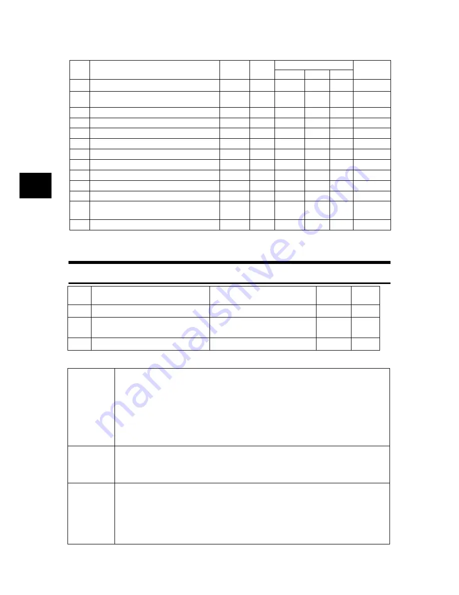
Control Gain and Filter Setting Parameter
4
Control mode
No.
PA1_
Name
Default
value
Power
Position
Speed Torque
Record of
reference value
84
Vibration suppressing anti resonance frequency 3
300.0 -
- -
85
Vibration suppressing workpiece inertia ratio
(vibration suppressing resonance frequency) 3
0 -
- -
86
Vibration suppressing damping coefficient
0.0000
-
- -
87
Model torque filter time constant
*** -
-
88
Position loop integration time constant
*** -
- -
89
Position loop integration limiter
0 -
- -
90
Load torque observer
0 -
-
91
P/PI automatic change selection
0 -
-
92
Speed range for friction compensation
10.0 -
-
93
Coulomb friction torque for friction compensation
0 -
-
94
Torque filter setting mode
1 -
-
95
Model torque calculation selection, speed observer
selection
3 -
-
96
Speed limit gain for torque control
4.0 - - -
Paremeters marked "
○
" in the table are enabled in the corresponding control mode.
4.3.2 Description of Each Parameter
PA1_51 to 53 Command filter settings
No. Name
Setting
range
Default
value
Change
51 Moving average S-curve time
0, 2 to 500 (×0.125 [ms])
***
Always
52
Low-pass filter (for S-curve) time
constant
0.0 to 1000.0 [ms]
0.0 Always
53 Command pulse smoothing function 0: Disable 1: Enable
0
Always
Filters can be added to commands for smoother follow-up.
Moving
average
S-curve time
This parameter is enabled under position control.
Specify the moving average S-curve filter time to position commands.
A larger setting at low command pulse frequencies or large electronic gear ratios can
reduce the torque ripple caused by fluctuation of the command pulse.
The new setting of this parameter is reflected when both the position command and
filter accumulation pulse are "0".
If PA1_13 (tuning mode selection) is 10 (auto tuning), 11 (semi-auto tuning) or
15(shorter cycle time operation mode) automatic adjustment is made inside the
amplifier.
Low-pass
filter (for
S-curve)
time constant
Enter the low-pass filter (for S-curve) filter time constant in relation to position
commands and speed commands. Acceleration and deceleration are made so that an
approximate S-curve is drawn.
Command
pulse
smoothing
function
The parameter is enabled under position control.
If the function is enabled, smoothing is added to the position command every 2 ms
intervals.
A larger setting at low command pulse frequencies or large electronic gear ratios can
reduce the torque ripple caused by fluctuation of the command pulse.
While the setting can be changed at any time, the new setting is reflected when both
the position command and filter accumulation pulse are "0".
Summary of Contents for ALPHA5 Smart
Page 1: ...24C7 E 0016c FUJI SERVO SYSTEM ALPHA5 Smart USER S MANUAL...
Page 2: ......
Page 4: ...ii...
Page 36: ...CHAPTER 0 INTRODUCTION 0 16 Combination between Servomotor and Servo Amplifier 0...
Page 276: ...CHAPTER 4 PARAMETER 4 108 Output Terminal Function Setting Parameter 4...
Page 368: ...CHAPTER 6 KEYPAD 6 56 Test Operation Mode 6...
Page 392: ...CHAPTER 7 MAINTENANCE AND INSPECTION 7 24 Troubleshooting 7...
Page 472: ...CHAPTER 11 ABSOLUTE POSITION SYSTEM 11 8 Calculation of Battery Life 11...
Page 488: ...CHAPTER 12 POSITIONING DATA 12 16 Response Time 12...
Page 592: ...CHAPTER 14 PC LOADER 14 48 Parameter Conversion Tool 14 1 2 3 4 6 7 8 9 10 11...
Page 633: ...CHAPTER 15 APPENDIXES Product Warranty 15 41 15 15 9 Product Warranty...
Page 634: ...CHAPTER 15 APPENDIXES 15 42 Service Network 15 15 10 Service Network...
Page 635: ......


