CHAPTER 2 WIRING
Description of I/O Signals
2-43
2
Teaching: Sequence input signal (Reference value 35)
The current position of the servomotor is written to the position data in the positioning data.
This function is enabled only if “7” (positioning operation) is selected for parameter PA1_01.
Function
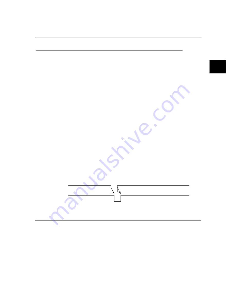
The command current position of the servomotor is written to the position data in the positioning
data at the rising edge of a teaching signal.
The current command position of the servomotor is written in the positioning data at the rising
edge of the teaching signal. The status of the position is absolute (ABS).
The signal can be always executed without relations to the status of the forced stop and servo-on
signals.
You can check the over write completion signal, one of sequence output signals, to check if
overwriting of the current position is completed.
Teaching is executed generally according to the following procedure.
(1) Designate the address of positioning data, to which the current position is to be written,
among AD0 to AD3.
(2) Using the manual forward rotation command, pulse operation or the like, feed the mechanical
system to the target position.
(3) The command current position of the servomotor is written to the position data in the
positioning data at the rising edge of a teaching signal. When the teaching signal is turned off,
the over write completion signal is turned off, too.
Parameter
setting
To assign the teaching signal to a sequence input terminal, enter the corresponding value (“35”) to
the input terminal function setting parameter.
Control mode selection: Sequence input signal (Reference value 36)
To switch the control mode.
Function
This function is to be used to switch to the control mode (control state) during servomotor
operation.
Turn the control mode selection signal, which is assigned to a CONT input signal, on or off to
switch the control mode.
Control mode selection is enabled only if PA1_1 (control mode selection) is set at 3, 4 or 5.
OFF
Over write
completion
OFF
Teaching
Summary of Contents for ALPHA5 Smart
Page 1: ...24C7 E 0016c FUJI SERVO SYSTEM ALPHA5 Smart USER S MANUAL...
Page 2: ......
Page 4: ...ii...
Page 36: ...CHAPTER 0 INTRODUCTION 0 16 Combination between Servomotor and Servo Amplifier 0...
Page 276: ...CHAPTER 4 PARAMETER 4 108 Output Terminal Function Setting Parameter 4...
Page 368: ...CHAPTER 6 KEYPAD 6 56 Test Operation Mode 6...
Page 392: ...CHAPTER 7 MAINTENANCE AND INSPECTION 7 24 Troubleshooting 7...
Page 472: ...CHAPTER 11 ABSOLUTE POSITION SYSTEM 11 8 Calculation of Battery Life 11...
Page 488: ...CHAPTER 12 POSITIONING DATA 12 16 Response Time 12...
Page 592: ...CHAPTER 14 PC LOADER 14 48 Parameter Conversion Tool 14 1 2 3 4 6 7 8 9 10 11...
Page 633: ...CHAPTER 15 APPENDIXES Product Warranty 15 41 15 15 9 Product Warranty...
Page 634: ...CHAPTER 15 APPENDIXES 15 42 Service Network 15 15 10 Service Network...
Page 635: ......


