


CHAPTER 2 WIRING
2-56
Description of I/O Signals
2
Anti resonance frequency selection 0: Sequence input signal (Reference value 57)
Anti resonance frequency selection 1: Sequence input signal (Reference value 58)
Select the anti resonance frequency, which is a vibration suppressing control function.
Function
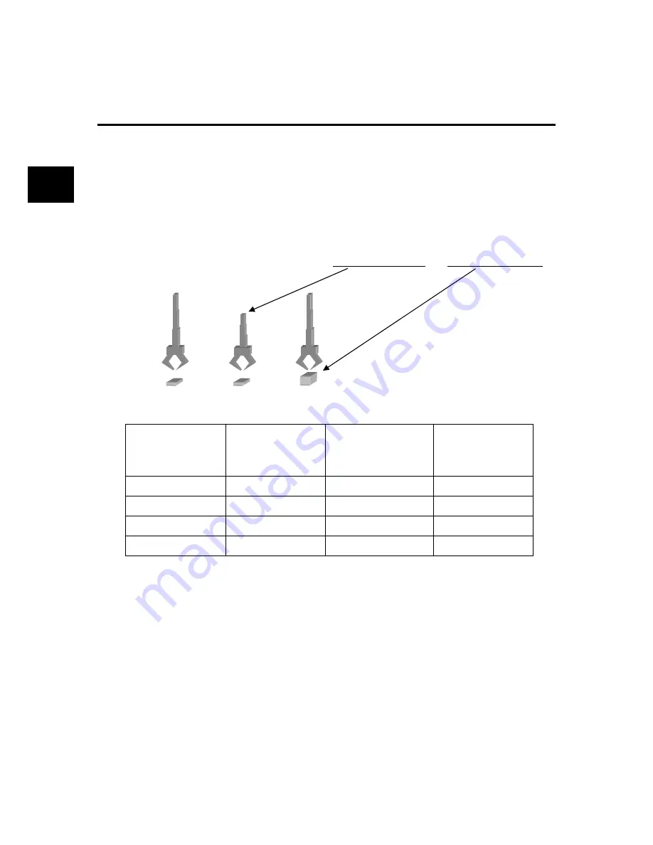
In a spring characteristic structure such as the robot arm and transfer machine, vibration is caused
at the end of the workpiece upon sudden acceleration or deceleration of the motor. Vibration
suppressing control aims at suppression of vibration of the workpiece in such a system, thereby
realizing positioning at a shorter cycle time.
Four points through combination of anti resonance frequency selection 0 and anti resonance
frequency selection 1 can be specified.
The anti resonance point may vary according to the length of the arm and the weight of the load.
Selection of the anti resonance frequency is shown in the table below.
Anti resonance
frequency selection 1
Anti resonance
frequency selection 0
Vibration suppressing
resonance frequency
Vibration suppressing
workpiece inertia ratio
OFF OFF PA1_78
PA1_79
OFF ON PA1_80
PA1_81
ON OFF
PA1_82
PA1_83
ON ON
PA1_84
PA1_85
Parameter
setting
To assign anti resonance frequency selection 0 or anti resonance frequency selection 1 to the
sequence input terminals, specify the corresponding value ("57" or "58") to the input terminal
function setting parameter.
If these signals are not assigned to the sequence input signals, they are treated as “always OFF”.
Therefore, PA1_78 (vibration suppressing anti resonance frequency 0) is always enabled.
To disable the anti resonance frequency, set the anti resonance frequency at 300.0 Hz.
Because in-cycle switching of the anti resonance frequency causes a shock, switch during
stoppage without fail.
In addition, it is recommended to use PA1_52 (low-pass filter (for S-curve) time constant) in
parallel.
(a) (b)
(c)
Summary of Contents for ALPHA5 Smart
Page 1: ...24C7 E 0016c FUJI SERVO SYSTEM ALPHA5 Smart USER S MANUAL...
Page 2: ......
Page 4: ...ii...
Page 36: ...CHAPTER 0 INTRODUCTION 0 16 Combination between Servomotor and Servo Amplifier 0...
Page 276: ...CHAPTER 4 PARAMETER 4 108 Output Terminal Function Setting Parameter 4...
Page 368: ...CHAPTER 6 KEYPAD 6 56 Test Operation Mode 6...
Page 392: ...CHAPTER 7 MAINTENANCE AND INSPECTION 7 24 Troubleshooting 7...
Page 472: ...CHAPTER 11 ABSOLUTE POSITION SYSTEM 11 8 Calculation of Battery Life 11...
Page 488: ...CHAPTER 12 POSITIONING DATA 12 16 Response Time 12...
Page 592: ...CHAPTER 14 PC LOADER 14 48 Parameter Conversion Tool 14 1 2 3 4 6 7 8 9 10 11...
Page 633: ...CHAPTER 15 APPENDIXES Product Warranty 15 41 15 15 9 Product Warranty...
Page 634: ...CHAPTER 15 APPENDIXES 15 42 Service Network 15 15 10 Service Network...
Page 635: ......


