


CHAPTER 4 PARAMETER
4-30
Control Gain and Filter Setting Parameter
4
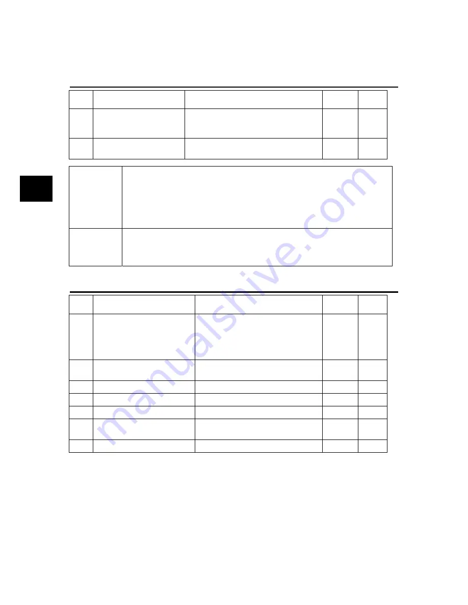
PA1_59 Torque filter time constant for position and speed control
PA1_60 Torque filter time constant for torque control
No. Name
Setting
range
Default
value
Change
59
Torque filter time constant
for position and speed
control
0.00 to 20.00 [ms]
***
Always
60
Torque filter time constant
for torque control
0.00 to 20.00 [ms]
0.00
Always
Torque filter
time constant
for position and
speed control
This parameter is enabled under speed and position control.
Add a filter to internal torque commands.
The response of the servo system is improved and resonance is suppressed. In
particular, the reference value should be larger with large load inertia.
Automatic adjustment is made inside the amplifier in other than the manual tuning
mode.
Set PA1_94 at 0 to allow manual settings.
Torque filter
time constant
for torque
control
The parameter is enabled under torque control. Add a filter to external torque
commands. Good effects can be expected for a system prone to electric noise or
one with fluctuation in the command voltage.
PA1_61 to 67 Second gain settings
No. Name
Setting
range
Default
value
Change
61 Gain changing factor
0: Position deviation (x10)
1: Feedback speed
2: Command speed
3: External switch (CONT signal
switch)
1 Always
62
Gain changing level
PA1_61=0:1 to 1000 [pulse]
PA1_61=1,2:1 to 100 [r/min]
50 Always
63 Gain changing time constant
0 to 100 [ms]
1
Always
64 Position loop gain 2
30 to 200 [%]
100
Always
65 Speed loop gain 2
30 to 200 [%]
100
Always
66
Speed loop integration time
constant 2
30 to 200 [%]
100 Always
67 Feed forward gain 2
30 to 200 [%]
100
Always
The gain of the servo system is switched from the first gain (PA1_55 to _58) to the second gain
(PA1_64 to _67).
Noise and vibration during stoppage can be reduced through gain switching.
Select the gain changing factor with PA1_61.
The unit of the reference value of the second gain (PA1_64 to _67) is "%." Specify the ratio to the first
gain.
[Example] If PA1_56 (speed loop gain 1) is 100 Hz and PA1_65 (speed loop gain 2) is 80%, the
second gain is 80 Hz. PA1_64 (position loop gain 2) is similar. If PA1_57 (speed loop
integration time constant 1) is 20 ms and PA1_66 (speed loop integration time constant 2) is
50%, integration time constant 2 is 40 ms.
Summary of Contents for ALPHA5 Smart
Page 1: ...24C7 E 0016c FUJI SERVO SYSTEM ALPHA5 Smart USER S MANUAL...
Page 2: ......
Page 4: ...ii...
Page 36: ...CHAPTER 0 INTRODUCTION 0 16 Combination between Servomotor and Servo Amplifier 0...
Page 276: ...CHAPTER 4 PARAMETER 4 108 Output Terminal Function Setting Parameter 4...
Page 368: ...CHAPTER 6 KEYPAD 6 56 Test Operation Mode 6...
Page 392: ...CHAPTER 7 MAINTENANCE AND INSPECTION 7 24 Troubleshooting 7...
Page 472: ...CHAPTER 11 ABSOLUTE POSITION SYSTEM 11 8 Calculation of Battery Life 11...
Page 488: ...CHAPTER 12 POSITIONING DATA 12 16 Response Time 12...
Page 592: ...CHAPTER 14 PC LOADER 14 48 Parameter Conversion Tool 14 1 2 3 4 6 7 8 9 10 11...
Page 633: ...CHAPTER 15 APPENDIXES Product Warranty 15 41 15 15 9 Product Warranty...
Page 634: ...CHAPTER 15 APPENDIXES 15 42 Service Network 15 15 10 Service Network...
Page 635: ......


