MPH-02, MPB-02, MPD-02
Drive Functions
8-67
DOK-INDRV*-MP*-02VRS**-FK01-EN-P
mm
mm
mm
mm
mm
mm
mm
mm
mm
b
034620
.
0
2
13850
3
5
.
479
2
)
0
.
185
(
2
16025
*
3
2
025
.
3
*
0
.
185
2
16025
*
005
.
0
−
=
−
=
−
−
=
Fig. 8-60:
Auxiliary equation 2
mm
mm
x
83
.
58
0005884
.
0
)
034620
.
0
(
0
=
−
−
=
Fig. 8-61:
Reference position
In order to be able to determine the reference position as exactly as
possible, several series of measurements should be recorded at different
temperatures for position-dependent temperature correction.
The resulting reference position is determined by the arithmetical mean of
the calculated reference positions.
The value for
P-0-0406, Axis correction temperature factor pos.-
dependent
is determined
•
by means of the data of the mechanical transmission elements
- or -
•
by means of series of measurements for actual position value error at
different temperatures at an identical axis position.
To determine the position-dependent temperature factor it is necessary to
record a series of measurements of correction values at different
temperatures, at least at one position that clearly differs from the
reference position.
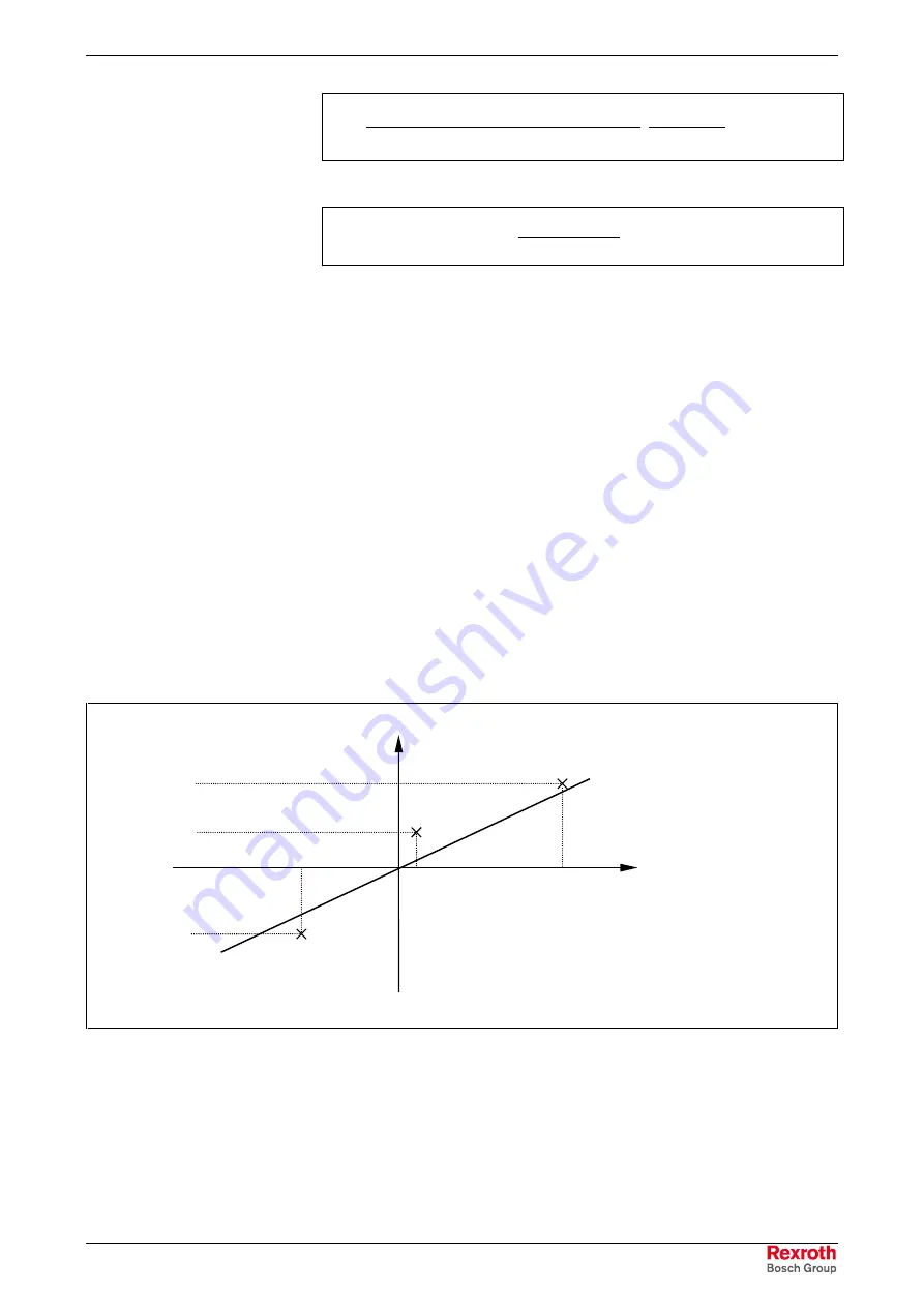
Depending on the temperature difference, a straight line can be
approximated through the measuring points.
correction value x
k
temperature
difference (
∆
T)
P
1
(
∆
T
1
,x
k1
)
P
2
(
∆
T
2
,x
k2
)
P
3
(
∆
T
3
,x
k3
)
x
k3
x
k2
x
k
1
∆
T
3
∆
T
2
∆
T
1
x
kn
:
correction value (measured position value – actual position value
(S-0-0051/S-0-0053))
∆
T
n
:
temperature difference
(measured temperature – reference temperature (P-0-0402))
Fig. 8-62:
Approximated straight correction line on the basis of measured
correction values at different
∆
T with identical actual position
Position-Dependent
Temperature Factor
Temperature Factor by Means of
Series of Measurements
Courtesy
of
CMA/Flodyne/Hydradyne
▪
Motion
Control
▪
Hydraulic
▪
Pneumatic
▪
Electrical
▪
Mechanical
▪
(800)
426-5480
▪
www.cmafh.com


