5-12
Motor, Mechanical Axis System, Measuring Systems
MPH-02, MPB-02, MPD-02
DOK-INDRV*-MP*-02VRS**-FK01-EN-P
•
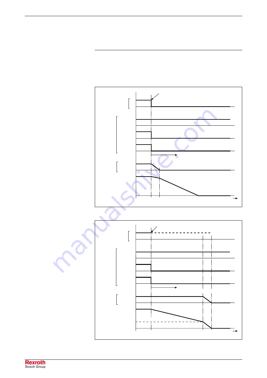
In the case of main drives, the internal drive enable is
switched off immediately. The drive coasts to stop. After
the velocity has fallen below the minimum value, the
holding brake is applied.
In the case of error situation 2, the drive becomes torque- or force-free
after the error event. The braking effect, in addition to the axis friction, can
only be achieved by means of the holding brake. To limit the damage the
holding brake is controlled depending on the application (servo or main
drive).
released
applied
1
0
(AF internal)
DK000011v01_en.fh7
bit 3: 1
0
motor
holding
brake
P-0-0115
bit 14: 1
0
bit 15: 1
0
AF from NC
F8-error or "torque disable"
error reaction
drive disables NC command values
actual velocity
value
t
Fig. 5-7:
Holding brake control with error situation 2 for servo drives
released
applied
1
0
(AF internal)
DK000012v01_en.fh7
bit 3: 1
0
motor
holding
brake
P-0-0115
bit 14: 1
0
bit 15: 1
0
AF from NC
drive disables NC command values
actual velocity
value
10 min
-1
bzw. 10 mm/min
F8-error or "torque disable"
error reaction
t
Fig. 5-8:
Holding brake control with error situation 2 for main drives
Holding Brake Control with Error
Situation 2
Courtesy
of
CMA/Flodyne/Hydradyne
▪
Motion
Control
▪
Hydraulic
▪
Pneumatic
▪
Electrical
▪
Mechanical
▪
(800)
426-5480
▪
www.cmafh.com


