8-16
Drive Functions
MPH-02, MPB-02, MPD-02
DOK-INDRV*-MP*-02VRS**-FK01-EN-P
DF0077v1.fh7
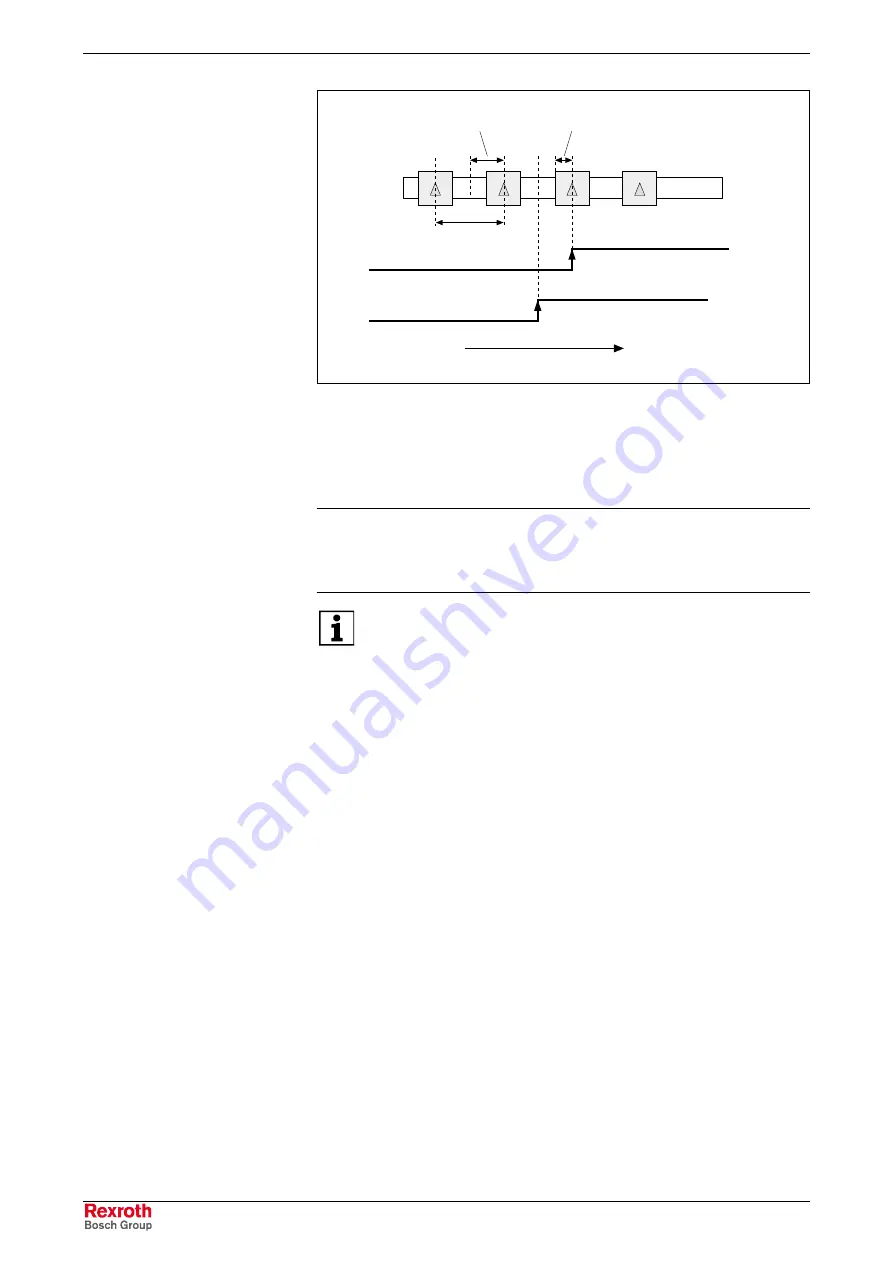
reference travel direction
home switch signal
detection in critical range
home switch signal
detection in allowed range
distance of
reference marks
optimum distance =
0.5 x distance of
reference marks
critical distance =
0.25 x distance of
reference marks
Fig. 8-14:
Critical and optimum distance between home switch and reference
mark
To monitor the distance home switch-reference mark the optimum
distance has to be preset in parameter
P-0-0153, Optimum distance
home switch-reference mark
.
Note:
When using the motor encoder for Rexroth motors of the
MHD, MKD, MKE, MSK, MSH, MAD and MAF series the
optimum distance is automatically calculated internally. The
value for P-0-0153 has to be left in its default status!
For default values of P-0-0153 for distance monitoring home
switch-reference mark see separate documentation "Parameter
Description for IndraDrive Drive Controllers"
During each homing procedure with home switch evaluation the
difference between actual distance and optimum distance is monitored by
home switch edge and reference mark. The difference is stored in
parameter
S-0-0298, Reference cam shift
. For optimum setting of the
home switch it can be mechanically shifted by the value of S-0-0298.
The distance between home switch edge and reference mark can also be
optimized drive-internally without mechanical shifting. The controller then
shifts the activation of the reference mark evaluation after detection of the
home switch edge by the value in
S-0-0299, Home switch offset
. For
this purpose the value of S-0-0298 has to be entered in S-0-0299.
Distance Correction
Courtesy
of
CMA/Flodyne/Hydradyne
▪
Motion
Control
▪
Hydraulic
▪
Pneumatic
▪
Electrical
▪
Mechanical
▪
(800)
426-5480
▪
www.cmafh.com


