7-76
Operating Modes
MPH-02, MPB-02, MPD-02
DOK-INDRV*-MP*-02VRS**-FK01-EN-P
Note:
For sequential block chains this is the last active block of the
sequential block chain. For single blocks (no sequential
block processing) the contents of parameters
P-0-4052
and
P-0-4053
are always equal!
•
P-0-4057, Positioning block, input linked blocks
→
contains an image of the digital sequential block inputs (switch cam
inputs)
Diagnostic Messages
In positioning block mode the following diagnostic messages can be
generated:
•
E0248 Interpolation acceleration = 0
•
E0249 Positioning velocity >= S-0-0091
•
E0253 Target position out of travel range
•
E0254 Not homed
•
E2055 Feedrate override S-0-0108 = 0
•
E2058 Selected process block is not programmed.
•
E2064 Target position out of num. range
•
F2028 Excessive deviation
7.8 Synchronization
Modes
Basic Functions of the Synchronization Modes
Brief Description
The synchronization modes allow the drive to run synchronously with
regard to a real or virtual master axis. The synchronization modes are
divided into the following two groups:
•
velocity synchronization
with real/virtual master axis
•
synchronous position control modes
•
phase synchronization with real/virtual master axis
•
electronic cam shaft with real/virtual master axis
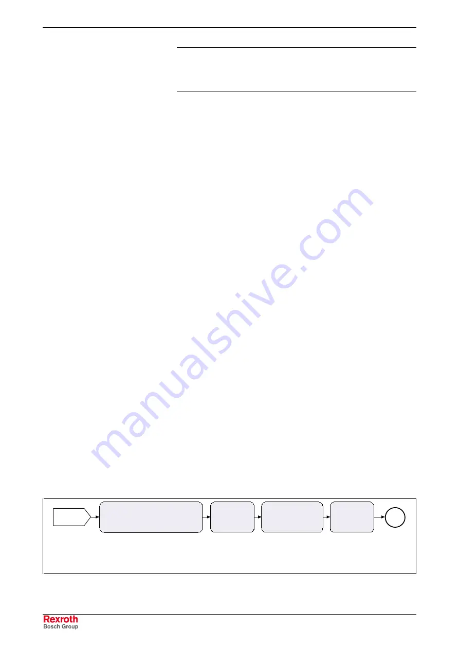
The figure below illustrates how the synchronization modes are integrated
in the control loop structure.
torque/force
command value
velocity com-
mand value
internal
command
value
master
axis pos.
command value adjustment for
synchronization modes
position
loop
1)
current loop
1)
... position loop not in "velocity synchronization" mode
DF000095v01_en.fh7
M
velocity loop
Fig. 7-45:
"Synchronization modes" block diagram
Courtesy
of
CMA/Flodyne/Hydradyne
▪
Motion
Control
▪
Hydraulic
▪
Pneumatic
▪
Electrical
▪
Mechanical
▪
(800)
426-5480
▪
www.cmafh.com


