2.
Add a front unit of the type PWS-6 to the left-hand frame of the three-frame window of the Configuration Dialog.
Either use the “drag and drop” method to drag the PWS-6 out of the category Front Units of the PWS objects
library or select the entry “Add PWS-6” from the left-hand frame’s contextual menu in the window.
3.
Select the first Control on the top of the added PWS-6 using the left mouse button. As an alternative, select the
Control by choosing the entry “Button 1” from the SELECT PWS CONTROL dropdown menu.
4.
Use the BUTTON TYPE dropdown menu to assign the button type “Radio Group” to the selected Control.
5.
Enter "1,2,3,4" into the ON VALUE input field. This defines the size of the group as four and at the same time the
parameter value set by each of the four radio buttons. The ON VALUE is set automatically for all members of the
radio group.
6.
Enter 0 into the OFF VALUE input field. This is the parameter to be set when no button is pressed. The OFF VALUE
is set automatically for all members of the radio group.
7.
Click on button MODIFY FUNCTIONS / CONNECTIONS and select function "Input" and connection
"N8000_1.DSP.Router_1.Output1". The function and connection is set automatically for all members of the radio
group.
8.
Enter the name of the signal at input 1 of the Router into the LABEL input field, e.g. "DVD".
9.
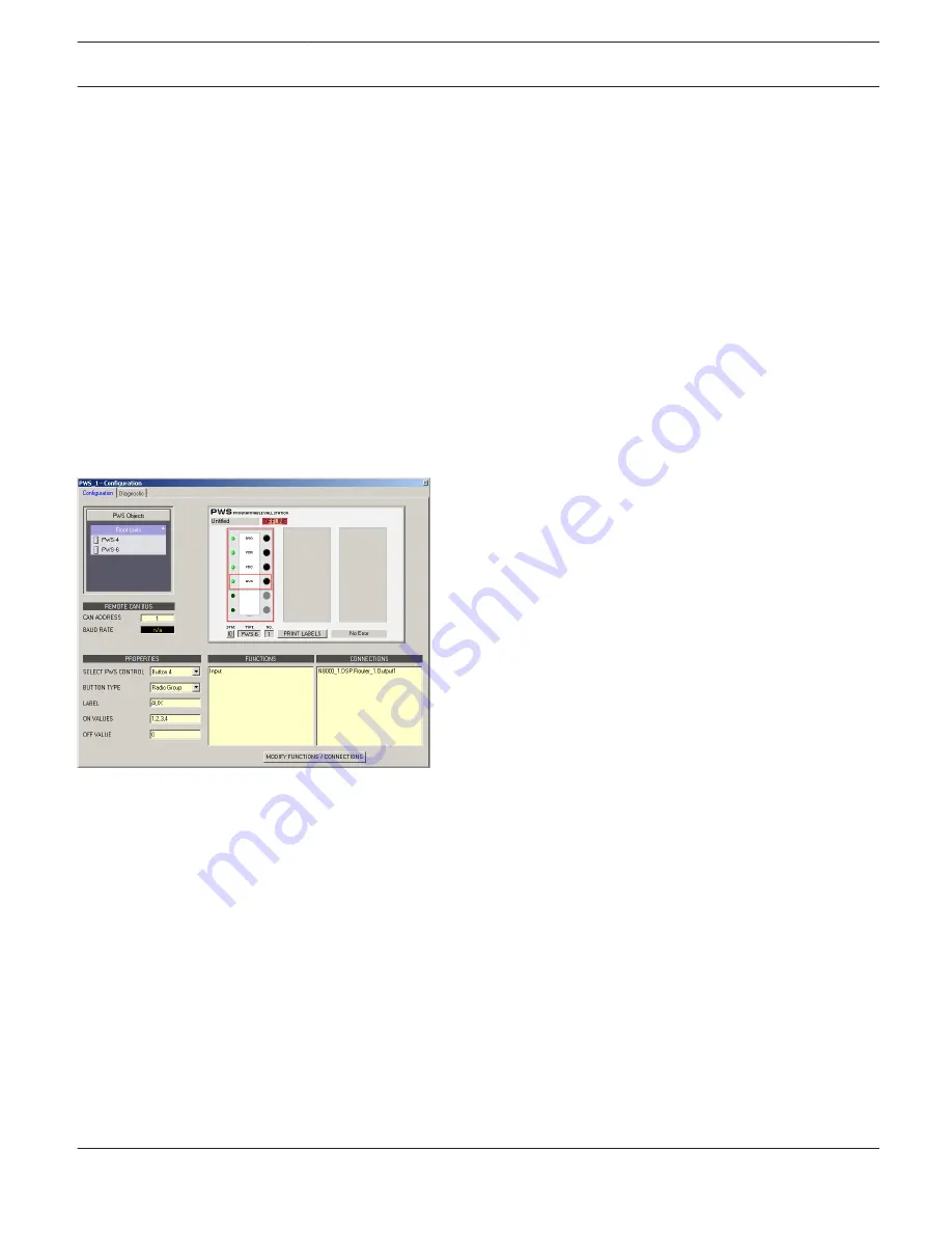
Repeat step 9 for buttons 2, 3 and 4. Enter the corresponding signal names (e.g. VCR, MIC, AUX) ein. The
following illustration shows the Configuration Dialog after configuration of the radio group is finished.
Switch Button
A Switch Button represents a regular switch, i.e. the switch setting changes every time when switching from ON to OFF
or from OFF to ON. Otherwise, the current state is remained (latching button). The following example for the usage of
the BUTTON TYPE “Switch Button” shows how to configure the buttons of a PWS-6 to be able to select different sound
reinforcement zones of a building. Therefore, it is assumed that the IRIS-Net project includes a NetMax N8000
equipped with an AO-1 Analog Output Card, with the card’s outputs 1 to 3 representing the different areas in a
building. The upper three buttons of the PWS-6 shall serve to mute the corresponding output signals.
1.
Select “Configuration” from the contextual menu of the PWS Device in the IRIS-Net worksheet. The Configuration
dialog appears.
2.
Add a front unit of the type PWS-6 to the left-hand frame of the three-frame window of the Configuration Dialog.
Either use the “drag and drop” method to drag the PWS-6 out of the category Front Units of the PWS objects
library or select the entry “Add PWS-6” from the left-hand frame’s contextual menu in the window.
3.
Select the first Control on the top of the added PWS-6 using the left mouse button. As an alternative, select the
Control by choosing the entry “Button 1” from the SELECT PWS CONTROL dropdown menu.
4.
Use the BUTTON TYPE dropdown menu to assign the button type “Radio Group” to the selected Control.
5.
Enter „ROOM 1“ into the LABEL input field.
IRIS-Net
PWS PROGRAMMABLE WALL STATION | en 717
Bosch Security Systems B.V.
User Manual
2017.05 | 3.20 | F.01U.119.956


