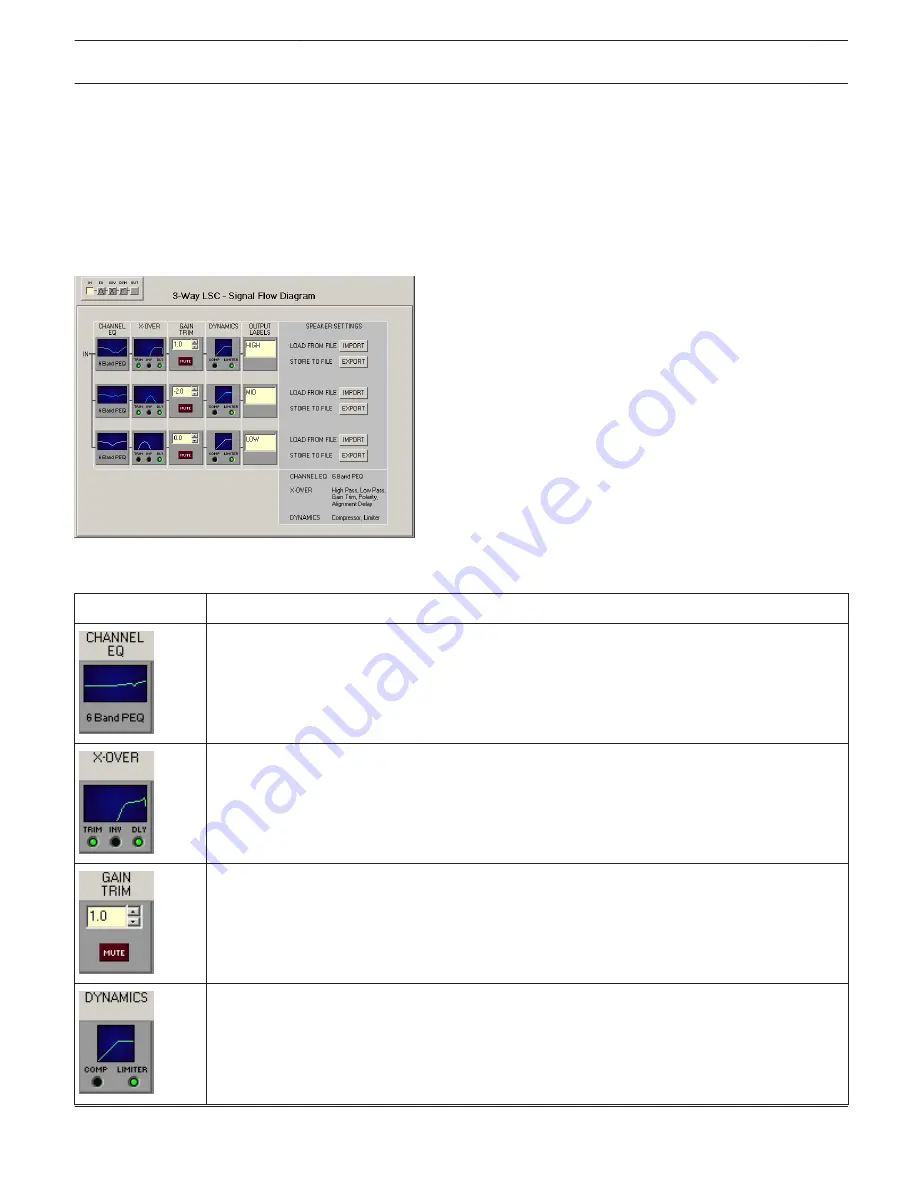
Flow Diagram
The FLOW DIAGRAM window shows a signal flow diagram, which offers quick overview of all DSP settings. Separately
muting, matching their levels amongst each other, and labeling channels is possible directly out of the diagram. All
other DSP parameters are accessible via clicking on the different function blocks. In addition, this window hosts all
necessary controls for storing and loading Speaker Settings.
Selecting the FLOW DIAGRAM window is possible by clicking onto the first or the fifth block in the Flow Diagram
Selector.
Function blocks
Element
Description
This block represents the 6 Channel EQs of the individual ways. The graph indicates the
frequency response of the Channel EQ Block. Simply clicking onto this block branches to the
CHANNEL EQ page.
This block represents the crossover of the corresponding way. The graph shows the frequency
response that results from the set X-Over parameters. Three additional LEDs signal the state of
trim, polarity and delay. Simply clicking onto this block branches to the X-OVER page.
This way allows separately setting the level. The setting is carried out via Up/Down Spin controls
or by directly entering a level value in dB. The MUTE button is used to attenuate the
corresponding way's signal. Clicking with the left mouse button on the MUTE button mutes the
corresponding way. The MUTE button is shown engaged and lights red. Again clicking onto the
button with the left mouse button deactivates the Mute function and the way is active.
This block represents the dynamics functions of the corresponding way. Two LEDs indicate
whether compressors or limiters are activated. The graph indicates set values. Simply clicking
onto this block branches to the DYNAMICS page.
IRIS-Net
DIGITAL MATRIX | en 423
Bosch Security Systems B.V.
User Manual
2017.05 | 3.20 | F.01U.119.956


