background image


OFF, 20000 
Hz

RESPONSE: OFF, 6dB,
12dB/Q=0.5, 12dB/
Q=0.6,
12dB/Q=0.7, 12dB/
Q=0.8,
12dB/Q=1.0, 12dB/
Q=1.2,
12dB/Q=1.5, 12dB/
Q=2.0,
Bessel 12dB, 
Butterworth 12dB, 
Linkwitz/Riley 12dB, 
Bes- sel 18dB, 
Butterworth 18dB, 
Bessel 24dB, 
Butterworth 24dB, 
Linkwitz/Riley 24dB 
FREQ:
20 Hz...20 kHz

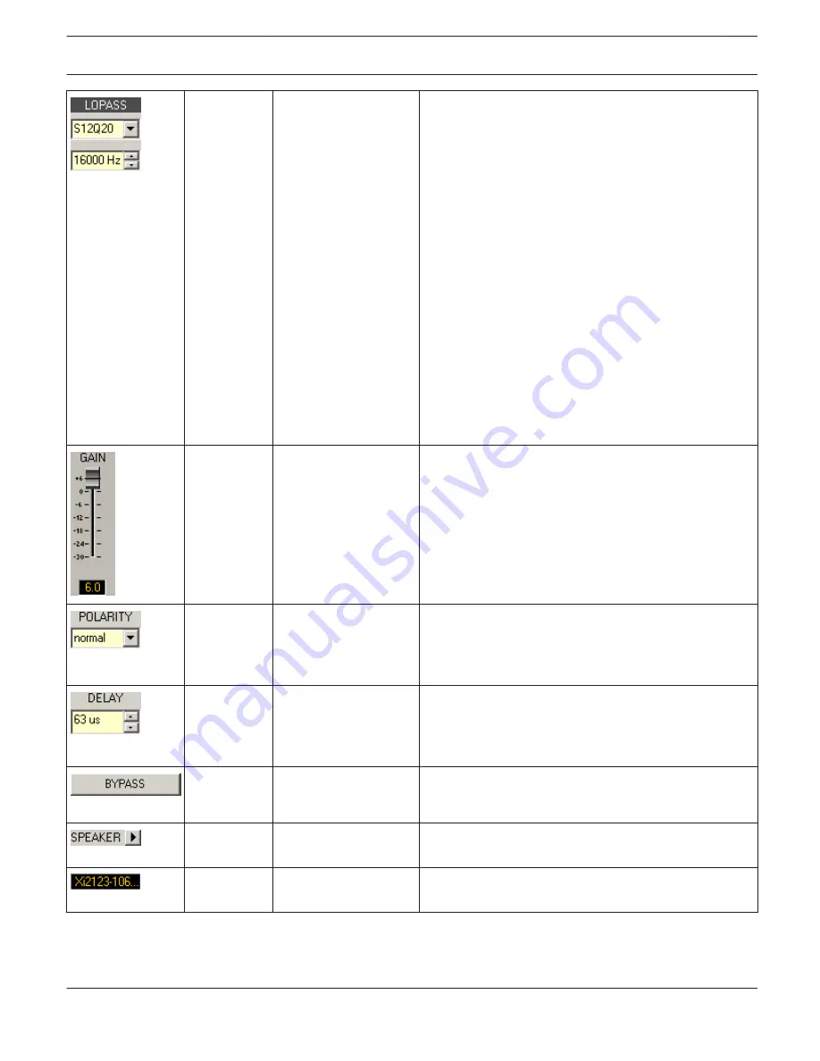
This parameter block represents the LOPASS filter. 
Setting different filter types (Bessel, Butterworth, 
Linkwitz/Riley) with slopes between 6 dB/Oct and 24 
dB/ Oct and cut-off frequencies between 20 Hz and 20 
kHz is possible.

0 dB

-30...+6 dB

GAIN TRIM is for increasing the level of the 
corresponding channel by up to 6 dB or attenuating it by 
upto 30 dB, it is used to match the output levels for each 
fre- quency band.


normal

normal, inverted

POLARITY allows inverting a channel, e.g. shifting its 
phase by 180°. Some cros- sover settings need phase 
inversion to prevent cancellations in the frequency 
response at the crossover frequency.


0 cm

0...68643 cm

DELAY is used to delay the signal of the corresponding 
way. Typically, this delay is used as time alignment delay 
to overcome the difference in distance between the 
loudspeaker components within a cabinet.


BYPASS activates (not engaged) or deactivates 
(engaged) the corresponding delay.


The arrow sign next to SPEAKER opens a dialog for 
selecting speaker files.


The text field shows the name of the currently loaded 
speaker file.


IRIS-Net

DIGITAL MATRIX | en 408

Bosch Security Systems B.V.

User Manual

2017.05 | 3.20 | F.01U.119.956

Summary of Contents for IRIS-Net

Page 1: ...IRIS Net en User Manual ...

Page 2: ......

Page 3: ... 529 5 1 TPI 5 529 5 2 TPI 8 TPI 12 540 6 DIGITAL SOUND PROCESSOR 549 6 1 DX38 Digital Sound Processor 549 6 2 DSP 244 576 6 3 DSP 600 FIR TUNE 603 6 4 Dx46 FIR DRIVE 649 6 5 Dx46 and DSP 600 694 7 PWS PROGRAMMABLE WALL STATION 710 7 1 PWS Device 710 7 2 Operation 711 7 3 Configuration 711 7 4 Button Types 714 8 PROMATRIX 8000 719 8 1 DPM 8016 Paging Manager 722 8 2 DPC 8000 Call Station 795 8 3 P...

Page 4: ...500 906 10 PAVIRO 911 10 1 PVA 4CR12 911 10 2 PVA 4R24 965 10 3 PVA 15CST 969 10 4 PVA CSK 982 10 5 PVA 2P500 987 IRIS Net Table of Contents en 4 Bosch Security Systems B V User Manual 2017 05 3 20 F 01U 119 956 ...

Page 5: ...nterfaces to optimally match any application offering easy control and monitoring even for large and complex installations and PA systems To get the most out of the IRIS Net software we recommend that you read through all the topics in this help file carefully Notes on The IRIS Net Documentation The left hand side of the Online Help allows convenient selection of individual chapters Chapters that ...

Page 6: ...ogram starts Follow the instructions of the installation program 5 When the installation is finished you can start IRIS Net from Windows via Start All Programs IRIS Net IRISNet IRIS Net Directory Structure This section provides information about IRIS Net directories and the contained files which after installing the software package are stored on your computer s hard disk IRIS Net s default instal...

Page 7: ...h the IRIS Net software Help This folder holds all help files These files have the extension htm Projects This directory is for saving your IRIS Net project files We recommend creating a separate project folder for every new project under the path Projects and to save all the files related to an individual project in the corresponding project folder Strictly following this convention greatly facil...

Page 8: ...eaker cabinets are located in this folder Speaker files contain measured transfer functions frequency response and phase response of loudspeaker systems IRIS Net lets you import and display this data This allows the user to see the frequency and phase response of set filter x over level phase and delay parameters as well as the resulting acoustical transfer function of DSP parameters in use with t...

Page 9: ... using the IRIS Net Project Generator execute the file setup exe User Controls The preconfigured control panels contained in this directory can be utilized in IRIS Net projects The control panels consist of one or more controls and a bitmap picture to provide graphical display of the panel The functions of each control come factory preconfigured so that activating a control panel is a matter of si...

Page 10: ... are able to make the desired settings It is also here that you can specify which panel opens by double clicking the group icon Creating groups is always recommended when several power amps or power amp channels are to be controlled or configured simultaneously Typical examples are System Group Switching On Off Change Presets Master EQ HF LF Groups Uniform configuration for X Over and speaker syst...

Page 11: ...Over with Level Trim and Alignment Delay as well as Dynamic functions including compressors and limiters On the Speaker page you are able to select loudspeaker files with measured frequency and phase responses and assign them to individual power amplifier channels This response plots can be displayed in EQ and X Over windows to allow optimized parameter settings Load provides information about mea...

Page 12: ... This ensures that all parameter values of all devices within a group are identical 9 Creating Additional Pages Open the Configuration Dialog by clicking the right mouse button while the cursor is located over the worksheet window Use the left mouse button and click on Add Layer This creates a new page layer Now you have to name it e g Control Page IRIS Net allows the use of up to 32 layers 10 Des...

Page 13: ...ghts Specifying at least an administrator password and protecting the configuration page against unwanted access is generally recommended How to edit an existing project This paragraph explains how to edit a project that already exists Due to the fact that IRIS Net provides the possibility for different users to have different access permissions assigned within a single project editing options mig...

Page 14: ...mplifier Presets Additionally reads the presets of all connected Remote Amplifiers Send All to Selected Devices Writes the DSP configuration and all settings into memory of connected devices Save Amplifier Presets Additionally writes the presets of all Remote Amplifiers RCM 24 Save Current DSP Settings to Reserved User Memory U01 Additionally writes the current DSP settings into the User Memory U0...

Page 15: ...presets into memory of the Remote Amplifier s Additionally writes the current DSP settings into the User Memory U01 of all Remote Amplifiers with RCM 24 Remote Control Module installed Project Password Protection The Password Database Window allows creating new user accounts It is possible to grant or to deny a user access to specific layers within a project IRIS Net IRIS Net en 15 Bosch Security ...

Page 16: ...ccount is being used The layers that can be accessed by the user Creates a new user account and adds it to the List of Users Deletes the user s that have been selected marked in the List of Users This field allows entering the user s name CAUTION A user name may not contain a comma This field allows entering a password for the user CAUTION A user name may not contain a comma IRIS Net IRIS Net en 1...

Page 17: ...re interrelated Opens the Layers Window which allows selecting those layers that are accessible for a user Keeps the changes that have been made and closes the window Discards the changes that have been made and closes the window The Layers dialog allows selecting the layers that are accessible for the selected user IRIS Net IRIS Net en 17 Bosch Security Systems B V User Manual 2017 05 3 20 F 01U ...

Page 18: ...et worksheet The dialog box for entering the text opens automatically Object List categories can also be accessed from the Configuration menu or the Configuration Dialog Box click right mouse button in the worksheet and be displayed in an individual window For detailed explanation of elements and their utilization please refer to the according chapters Adding Devices Devices are units and componen...

Page 19: ...on shows how to add a P3000RL power amp to an IRIS Net project The following table lists the possible settings that are available in the Amplifier Dialog Element Description If an appropriate interface between PC and device already exists in the IRIS Net project you can select that interface from the drop down field Select an interface from the drop down field to automatically include it in the IR...

Page 20: ...sted interfaces are divided into groups to provide a better overview Opening and closing the group lists is possible through clicking on the arrow icon in the top right corner The content of the interfaces list depends on the actually installed IRIS Net version i e it may differ from the list as shown in the following illustration Element Description PCAN USB Interface UCC1 between USB port of a P...

Page 21: ...en two states e g On Off Parameter Controls Element Name Description Combo Box Windows Combo Box for selecting parameters or functions from a list Edit Edit field for entering and displaying values or text e g names Fader Fader for setting parameter values Bar Graph Bar graph display horizontal for graphical indication of parameter values e g operational states Knob Knob for setting parameter valu...

Page 22: ... g names LED LED indicator for signaling operational states or errors Meter Bar graph display vertical for graphical indication of parameter values e g meter instruments Scale Scale for labeling vertical bar graph indicators Image List Image List for switching between different images Advanced Controls Element Name Description MasterEQ PEQ user panel for a single or a group of Master EQs IRIS Net ...

Page 23: ...ic processors Mini MasterEQ Master EQ Block for displaying Equalizer settings Mini ChannelEQ Channel EQ Block for displaying Equalizer settings Mini XOver X Over Block for displaying Frequency Crossover settings XOver X Over user panel for a single or a group of Frequency Crossover blocks IRIS Net IRIS Net en 23 Bosch Security Systems B V User Manual 2017 05 3 20 F 01U 119 956 ...

Page 24: ...on and select Modify Properties from the switch button s contextual menu The Switch Button Class window appears 3 Edit the button s appearance and labeling in the Switch Button Class window 4 Click on the Modify Functions Connections button The Modify Functions Connections window appears 5 Enter power in the Filter text field using a filter is optional Only objects that include the parameter power...

Page 25: ...m to disc IRIS Net s preconfigured User Controls are to be found in the Objects Bar category User Controls and in the separate User Controls window This window opens when you choose Add User Control from the IRIS Net Configuration menu or from the contextual menu within the IRIS Net worksheet Using Drag Drop you can select User Controls from the list and include them in the IRIS Net worksheet to c...

Page 26: ...Description Amp_MUTE Supervision The MUTE A and MUTE B buttons activate ChA Mute or ChB Mute In the text field you can set the amp s CAN address In Standby or Protection mode the LED lights red Otherwise it lights green Possible Connections RCM 24 Amp Amp_MUTE_Panel The MUTE A and MUTE B buttons activate ChA Mute or ChB Mute A click on the amp itself opens the Amplifier Control Panel Possible Conn...

Page 27: ...orted line or when the unit is in Standby Protection or MUTE mode Otherwise the LED lights green Possible Connections RCM 24 Amp Master_EQ_Panel_01 Equalizer panel with label field for the RCM 26 Remote Amp Use the Master EQ button to open the Master EQ dialog Possible Connections RCM 24 Amp Channel Master_EQ_Panel_02 Equalizer panel with label field for the RCM 26 Remote Amp Use the Master EQ but...

Page 28: ...ion PowerH_Panel_01 In Online mode the LED light green Otherwise the LED light red The LEDs below the CAN address field light green yellow when the amplifiers is Power Standby mode ON button for switching the amp s power on or off Possible Connections RCM 26 Amp PowerH_Panel_02 In Online mode the LED light green Otherwise the LED light red The LEDs below the CAN address field light green yellow wh...

Page 29: ... and name of the currently active factory user owner memory is being indicated Possible Connections RCM 26 Amp RCM 26_Memory_Panel _01 Load user memory presets 1 6 or save to user memory 1 6 Number and name of the currently active user memory is being indicated Possible Connections RCM 26 Amp RCM 26_Memory_Panel _02 Load user memory presets 1 6 or save to user memory 1 6 User memory 1 is protected...

Page 30: ... Otherwise the LED lights green The white arrow buttons opens the Supervision Test or Load dialog of the amplifier Possible Connections RCM 26 Amp RCM 28 User Controls Following sets of connections are used in following table RCM 28 Amp TG 5 TG 7 H2500 H5000 RCM 28 Amp Channel TG 5 ChA TG 5 ChB TG 7 ChA TG 7 ChB H2500 ChA H2500 ChB H5000 ChA H5000 ChB Picture Name Description RCM 28_Group_Panel_01...

Page 31: ...0RT P1200RT RCM 24 Amp Channel P900RL ChA P900RL ChB P1200RL ChA P1200RL ChB P3000RL ChA P3000RL ChB P900RT ChA P900RT ChB P1200RT ChA P1200RT ChB RCM 26 Amp TG 5 TG 7 H2500 H5000 RCM 26 Amp Channel TG 5 ChA TG 5 ChB TG 7 ChA TG 7 ChB H2500 ChA H2500 ChB H5000 ChA H5000 ChB Picture Name Description Delay_Panel_01 Delay value and bypass for the channel delay X Over of a remote amp Possible Connecti...

Page 32: ...Amp RCM 26 Amp Group_Panel_02 These two LEDs indicate whether the limiter LIMIT or the compressor COMP of the DSP has been activated Fader and MUTE button for controlling the amplifier The LED bar graph meter is for monitoring the amp s output levels maximum of both channels Clicking onto the 0 marking resets the fader to 0 dB Possible Connections RCM 24 Amp RCM 26 Amp Group_Panel_03 Indicates the...

Page 33: ...ogMicIn ChX N8000 DSP Analog Out ChX N8000 DSP AutoMixer ChInX N8000 DSP AutoMixer ChOutX N8000 DSP CobraNetIn ChX N8000 DSP CobraNetOut ChX N8000 DSP DigitalIn ChX N8000 DSP LSpkBlock ChX N8000 DSP Matrix InputX N8000 DSP Matrix OutputX N8000 DSP MatrixRouter InputX N8000 DSP MatrixRouter OutputX N8000 DSP Mixer ChInX N8000 DSP Mixer ChOutX N8000 DSP PriorityMatrix InputX N8000 DSP PriorityMatrix...

Page 34: ...nter of the loudspeaker symbol lights red at the occurrence of the load at the amplifier s output going outside the range set by the minimum and maximum impedance values a open or shorted line or when the unit is in Protection or MUTE mode Otherwise the LED is invisible Possible Connections RCM 24 Amp Channel RCM 26 Amp Channel Sx300_State_01 The LEDs in the loudspeaker symbol light red at the occ...

Page 35: ...the minimum and maximum impedance values a open or shorted line Otherwise the LED lights green Possible Connections RCM 24 Amp RCM 26 Amp Testgenerator_01 Test tone generator panel with label field for the Remote Amplifier Possible Connections RCM 24 Amp RCM 26 Amp Matrix User Controls Picture Name Description Dante_Panel_ 01 Selection of Dante device and Dante channel MUTE button and editable cha...

Page 36: ...ixer ChOutX N8000 DSP DigitalIn ChX Level_Panel_ 03 Fader MUTE button and INV button for controlling and LED bar graph meter for monitoring a microphone input level Additionally Gain MIC LINE button and Phantom Power button Possible Connection N8000 DSP AnalogMicIn ChX Interface User Controls Picture Name Description CAN_Interface_Sta te_01 Shows the momentary state of the CAN bus the amount of de...

Page 37: ... EOL_LED_Panel_0 2 The Short LED lights red if the voltage at the amplifier s output 5 6 7 or 8 is below the EOL VOLTAGE threshold set in the Supervision Test tab of the amplifier Otherwise the LED lights green The Open LED lights red if the current at the amplifier s output 5 6 7 or 8 is below the EOL CURRENT threshold set in the Supervision Test tab of the amplifier Otherwise the LED lights gree...

Page 38: ...uld uncheck all other checkboxes You can use the Filter in the Connections dialog to filter the list of available objects 4 Select the desired amplifier from the list and drag it over into the Connections field within the Panel Class window 5 Close the Connections for PowerH_Panel_01_1 window 6 You can edit the appearance of the User Control e g setting a background color or transparency in the Pa...

Page 39: ...S Net Bitmaps Folder Using custom designed bitmap graphics in file format bmp jpg or png within IRIS Net projects along with the ones that come with the software package is possible The color RGB 255 0 255 HTML ff00ff is reserved for defining areas within bitmap graphics that appear transparent within IRIS Net e g Rack_15HU You can copy new Bitmaps into IRISNet s Bitmaps Folder or you can add a ne...

Page 40: ... lists a selection of textboxes with different pre set font sizes To include a textbox in a project you just have to drag the box out of the list and drop it into the IRIS Net worksheet The following illustration shows the Textboxes window The table also provides a short description for each item listed Element Description MS Sans Serif 8 Textbox using Sans Serif font size 8 MS Sans Serif 12 Textb...

Page 41: ...viously selected file i e the operating system starts the program that is associated with the file and then opens the selected file Using Groups IRIS Net provides Groups as special control elements Groups are used for combining a variety of objects Actions applied to a group are applied to all objects of the group An object can be included in various groups at the same time Function specific group...

Page 42: ...ects an object class The drop down list displays all classes with at least one object contained in the current IRIS Net works heet All objects of the object class currently selected in the dropdown field class are added to the group Sets the font used for the group icon label in the IRIS Net worksheet IRIS Net IRIS Net en 42 Bosch Security Systems B V User Manual 2017 05 3 20 F 01U 119 956 ...

Page 43: ...he lower part of the window A single object can be selected by clicking on it with the left mouse button Several consecutive objects can be selected by selecting the first object then selecting the last object while pressing the Shift key simultaneously with the mouse click Individual objects can be toggled between selected and deselected by pressing the Ctrl key simultaneously with the mouse clic...

Page 44: ...ion greatly simplifies the design of projects which include layers with similar appearance Creating an object with its visibility flag unchecked for all layers hides the object from the entire project When editing the visibility of an object please proceed as follows 1 Highlight the object in the IRIS Net worksheet 2 Click the right mouse button to open the context menu of the selected object 3 Se...

Page 45: ...ion on the project author The COMMENT field provides space for a brief description of the project The Project Info Dialog is accessed by selecting the menu entry Info in the Main Menu Software update If a Internet connection is available updating IRIS Net is possible via Internet The Software Update Dialog is accessed by selecting the menu entry Search for Updates IRIS Net IRIS Net en 45 Bosch Sec...

Page 46: ...the update Show Notifications in Taskbar Check this option if notifications about software updates should be shown in the Taskbar Edit Application Settings The Settings dialog allows the user to edit attributes of IRIS Net Amongst others the user can specify whether and if so which events shall be included in the IRIS Net event log The Settings dialog is accessed from the menu Edit Settings IRIS N...

Page 47: ...event log Startup Layer for current project Specifies the layer that is shown when the project file is opened Active Layer after IRIS Net Screensaver Specifies the layer that is shown after the screensaver has been activated Using the SPL Calculator The SPL Calculator provides information about the theoretical SPL resulting from given equipment and given distance between speaker system and sound r...

Page 48: ...Clicking this soft key starts the calculation This field shows the resulting SPL in dB Clicking onto this button closes the SPL Calculator Limiter Threshold Calculator The Limiter Threshold Calculator provides information about the limiter threshold to be set for given equipment and given loudspeaker systems data The Limiter Threshold Calculator makes no claim to be pinpoint accurate i e results s...

Page 49: ...ter Threshold Calculator Using the Event Scheduler The Event Scheduler is divided into three windows On the Events tab you can create and edit nonrecurring as well as periodically recurring events The Day Programs tab allows creating lists of daily recurring events The Holiday tab lets you specify periods like for example school holidays during which an alternative Day Program shall be used instea...

Page 50: ... for this event Event type Double clicking on an event s corresponding entry in the event list allows changing the event type in the Event Parameters window Event parameter Double clicking on an event s corresponding entry in the event list allows changing the selected parameter in the Event Parameters window Macro to be executed in case of occurrence of the event Double clicking on an event s cor...

Page 51: ...ific time The event is scheduled to be hourly activated at a specific time min sec The event is scheduled to be activated every minute at a specific time seconds The event is scheduled to be activated on selected weekdays of each week and at a specific time The Macro Selection Dialog window allows selecting the macro to be executed on the occurrence of an event Day Programs This window allows crea...

Page 52: ...nt list Copy a single or various marked events from the event list Copied events can be pasted to the end of the event list Day Program List Selecting a Day Program displays a list of associated events which can be edited Left click on the name of a pre viously selected Day Program to enter a new name for this Day Program Event name Left click on the name of a previously marked event to enter a ne...

Page 53: ...ifferent holidays offers the possibility to execute various Day Programs during particular periods within a year Element Description New Holiday creates a new entry in the list of holidays New holidays are numbered in ascending order whereas the current date is set as standard once only period of a new holiday The holidays selected in the holiday list are being deleted Opens the Holiday Parameters...

Page 54: ...he holiday s corresponding entry in the holiday list allows selecting the Day Program to be executed in the Dayprog Selection Dialog window Saving of modified holidays in the holiday list The period corresponding to a holiday can be specified in the Holiday Parameters window A holiday always lasts a single day or several consecutive days A single day can be one specific date or a periodically recu...

Page 55: ... access to the Macros tab see below Triggers tab and Conditions tab Macros This window allows creating and editing macros Macros are used to change the status of objects Objects can be devices e g a N8000 System Controller as well as elements in IRIS Net e g controls IRIS Net IRIS Net en 55 Bosch Security Systems B V User Manual 2017 05 3 20 F 01U 119 956 ...

Page 56: ...Name of the macro Left click on the name of a previously selected macro to enter a new name for this macro The variable that is set when the macro is being executed The value that is assigned to the variable when the macro is being executed System internal identifier of the macro The Operation window allows selecting the variable for which the value is to be set by the macro A variable always cons...

Page 57: ...een selected in the func tions list are assigned to the macro that is currently being edited The object that has been selected in the object list is assigned to the macro that is currently being edited Closes the Operation window and returns to the Macros window The Object Parameters window allows entering the value that is to be assigned to a variable Triggers Triggers are used to execute macros ...

Page 58: ... pasted at the end of the Trigger List The name of the Trigger Left clicking on the name of a Trigger that has previously been selected in the Trigger List lets the user assign a new name to the Trigger The condition associated to the Trigger Double clicking on the Trigger s corresponding entry in the Trigger List lets the user select the condition to be assigned to the Trigger from the Condition ...

Page 59: ... status of the condition changes from false to true Equally the OFF Macro Selection Dialog Window lets the user select the macro that will be executed when the status of the condition changes from true to false IRIS Net IRIS Net en 59 Bosch Security Systems B V User Manual 2017 05 3 20 F 01U 119 956 ...

Page 60: ...er symbol indicates that the Condition is true The type of a Condition can be is equal is lower or timespan Double clicking on a Condition s corresponding entry in the Condition List lets the user select the type for the Condition in the Condition Properties Window The properties of a Condition Double clicking on a Condition s corresponding entry in the Condition List lets the user select the prop...

Page 61: ...escription Opens the Operation Window which lets the user select the variable objects and keywords that is to be used for the equation comparison The value that the selected variable has to equal or fall below The Operation Window lets the user select the variable whose value is relevant for the Condition A variable always con sists of an object and an associated function To select a variable the ...

Page 62: ...me the Condition is true exactly once for the Duration Starting immediately from the beginning of the Period of Time the Condition is recurringly true every x minute s during the Duration Starting immediately from the beginning of the Period of Time the Condition is recurringly true every x hour s during the Duration Starting immediately from the beginning of the Period of Time the Condition is re...

Page 63: ... from the beginning of the Period of Time the Condition is true for the Duration if the first day of the Period of Time falls on the selected x weekday of a month Otherwise starting from the beginning of the Period of Time the Condition is true on every selected x last weekday s of a month at start time of the Period of Time and for the Duration The Period of Time has a start time start time on a ...

Page 64: ... Scene has not been saved before This window allows assigning a name to a Scene Button No Changes applied to a Scene are not being saved Button Cancel Cancels the creation of a new Scene Creates a new entry in a Scene Deletes the currently marked entries of a Scene Lets the user edit the column entry Action of the selected Scene entry by opening the Operation dialog Lets the user edit the column e...

Page 65: ...Selecting the entry Device Scan in the Tools menu lets you access the Device Scan dialog Element Description Device Type List Shows the types of devices which upon pressing the SCAN button are accessible via Ethernet Selecting a list entry lists only devices of this specific type MAC ADDR Shows the MAC address of the detected devices INTERFACE Shows the interface of the detected devices DHCP Shows...

Page 66: ... the Config dialog box Clicking onto this button closes the Device Scan dialog Editing network settings Double click at the network settings of a device in the Devices list to open the dialog for editing the network settings Following table lists the default username and password for supported devices Device Firmware version Default user name Default password N8000 all netmax netmax P 64 all netma...

Page 67: ...onto an existing RCM 28 remote amplifier in the worksheet By doing this the existing RCM 28 remote amplifier will be renamed and linked to the dropped device IRIS NET NAME Double click to assign a IRIS Net device name to the OMNEO device MAC ADDR Shows the MAC address of the detected devices IP Shows the IP address of the detected devices SYSTEM ROLE Shows the system role of the device FIRMWARE VE...

Page 68: ...twork Close Clicking onto this button closes the OCA Scan dialog Using the PA Event Log The Event Log chronologically lists internal IRIS Net events and events that occurred during the operation of devices that are included in the project This for example aids when troubleshooting the system Element Description Devices Allows the selection of devices or device types to be included in the Event Lis...

Page 69: ... project to be monitored In addition this dialog offers the possibility to edit the logging characteristics of N8000s or DPM 8016s that are included in the project and the characteristics of the central logging file that is stored on the PC Element Description EVENT TYPES ERRORS WARNINGS INFORMATION N8000 P 64 or AUDIOEVENTS DPM 8016 Selection of event types to appear in the Event Log Selection of...

Page 70: ... at which when exceeded a new log file is being created Changing available devices The devices shown in the Object List can be customized Use the IRIS Net Device Options dialog window The dialog window opens automatically the first time IRIS Net is run For later customization you can find the dialog window in the menu Edit Device Options Select the groups of devices that should be available in the...

Page 71: ...ng several UCC1 s on a single CAN bus is also possible A total of up to 100 devices can be operated on a single CAN bus Since the CAN interfaces of all EV DC devices are galvanically isolated from the rest of the circuitry network cabling also carries a common ground conductor CAN_GND ensuring that all CAN interfaces in the network are connected to a common ground potential The UCC1 provides the p...

Page 72: ...aker so that an engineer can easily monitor the audio signal at the input or output of any amplifier on the network The CAN bus standard provides several different data transfer rates with the data rate being indirectly proportional to the bus cable length Small networks allow baud rates up to 500 kbit s For very large networks reducing the baud rate minimum 10 kbit s is necessary The following ta...

Page 73: ... resistors with higher impedance than the specified 120 Ω are recommended to reduce the ohmic load of the interface drivers and therefore the voltage drop bet ween the two cable ends The following table is meant for first assessment of necessary cable diameters for different bus lengths and bus par ticipant numbers Bus Length inm Number of Units on the CAN Bus 32 64 100 100 0 25 mm or AWG24 0 34 m...

Page 74: ...C The STATUS LED has to light as soon as the operating system recognizes the UCC1 IRIS Net has not yet been started As soon as the IRIS Net Software has been started the STATUS LED should blink indicating that the communication between the IRIS Net application and the UCC1 has been established Caution Make sure to install all necessary drivers before using the UCC1 Advice on how to install the dri...

Page 75: ...ted speaker systems To configure the Remote Power Amplifier System according to your requirements start the IRIS Net Software and open the corresponding project file Please also bear in mind the following chapters which lay out the procedures when creating and editing IRIS Net projects Set CAN baud rate 1 Changing Baud rate of P Series Remote Amplifiers for changing the Baud Rate to 10 kBit s powe...

Page 76: ...0 to 1 If Baud rate freeze is activated the baud rate can be changed neither via Address Switch nor via IRIS Net For changing baud rate you have to deactivate Baud rate freeze Caution The option Baud rate freeze must be used carefully Activate Baud rate freeze of a amplifier only if all amplifiers at a CAN network have the same baud rate and the baud rate will not be changed in the future Conseque...

Page 77: ...y used commands are arranged as buttons in the tool bar The button of a command that is not available is grayed out Clicking the button has no effect 4 Layer Selection Bar If a project file includes various layers switching between these layers is possible by selecting the corresponding tab in the Layer Selection Bar Left clicking on a previously selected tab allows renaming this tab Right clickin...

Page 78: ... an existing project Reload Ctrl R Reloads the current project Save Ctrl S Saves a project Save As Saves an existing project under another name Print Setup Change the printer and printing options Last used project files The last four projects used are listed here Exit Shuts the program down Menu Edit Element Shortcut Description Cut Ctrl X Removes the selected item s and places them on the clipboa...

Page 79: ...atus bar at the bottom of the IRIS Net workspace window Object List Shows the object list at the left of the IRIS Net workspace window IRIS Net IRIS Net en 79 Bosch Security Systems B V User Manual 2017 05 3 20 F 01U 119 956 ...

Page 80: ...ces IRIS Net allows the use of up to 32 layers Delete Layer A click on Delete Layer deletes the currently active page layer from the IRIS Net project CAUTION Delete Layer erases the entire contents of the currently active page However as long as the project is not saved all data is still present in the project file If you inadvertently have deleted a page use Reload to revert to the last saved pro...

Page 81: ...ment Description Configuration via CAN Hardware Opens the window Configuration Control Functions Opens the window Control Functions System Check Opens the window RCM 24 System Check Overview Opens the window RCM 24 Overview Menu RCM 26 Element Description Configuration via CAN Hardware Opens the window Configuration IRIS Net IRIS Net en 81 Bosch Security Systems B V User Manual 2017 05 3 20 F 01U ...

Page 82: ...me Clock for editing real time clock of all NetMax devices in the project Superblocks Opens the window Matrix Superblocks for deleting Superblocks Menu Element Description Project Info Opens the window Project Info Help Topics Opens IRIS Net help this document Quick Start Guide Opens the IRIS Net Quick Start Guide Search for Updates Opens the Software Update dialog About IRIS Shows the current app...

Page 83: ...e user is asked if he wants to keep the original version or take the current version including the modified parameters Controls PushButton The IRIS Net Control of the type PushButton is the equivalent of a button The button has two states pressed and unpressed Left clicking on the PushButton Control activates the pressed state The unpressed state is restored immediately after releasing the mouse b...

Page 84: ...unpressed FColor of the button label when in the unpressed state The button opens the Color dialog which allows selecting between predefined and user definable colors Font Displays the currently selected typeface for button labeling The button opens the Typeface dialog which allows selecting font type font style weight and font size Bitmap Displays the filename of the bitmap graphic file that is c...

Page 85: ...ton to be modified Closes cancels the PushButton Class dialog Opens the Properties for PushButton dialog Property Description bitmap Path and filename of bitmap used for button Path must be entered relative to IRIS Net caption Caption of button Capture accel Only used if mode is increment or decrement Every capture period ms the new value is calculated by new_value old_value capturea ccel Capture ...

Page 86: ...d Property click Type Format Example Comment Execute a file doc open path and file name doc open c alarm mp3 Every file type can be executed Microsoft Windows uses the default application depending on file extension for executing the file e g pdf Adobe Reader mp3 Winamp Absolute or relative path description is possible Set parameter value Device Keyword Value N8000_1 DSP AnalogIn_ 1 Ch3 Mute 1 Set...

Page 87: ...op freq Hz 200 ms impedancecurve 0 0 0 20 Hz 20000 The impedance test is executed at the RCM 24 remote amplifiers connected to the button Loads a preset in the device s RCM 24 amplifier RCM 26 amplifier Dx46 DSP 600 or N8000 P 64 connected to the PushButton LoadPreset preset number N8000 or P 64 LoadPreset 01 Remote Amplifier or Dx46 DSP 600 LoadPreset U01 Possible connections are the remote ampli...

Page 88: ...ed in the templates is given in the section of the corresponding device A selection of templates is described on the following pages Remote Amps UI The Remote Amps UI control panel is the equivalent of the Setup Control Window of an RCM 24 Remote Amplifier The control panel is accessed via a Push Button or a Group and is used for the synchronized control of various amplifiers The RCM 24 Remote Amp...

Page 89: ...fortably adjusting all the specific settings that are necessary for the operation of a single loudspeaker chassis or individual way of a loudspeaker system in a separate window All settings parameters can be saved in configuration files Speaker Settings Pre defined configuration files Speaker Settings are available for loudspeakers from Electro Voice and DYNACORD The Single Channel Group Dialog ca...

Page 90: ...block opens the CHANNEL EQ page Clicking with the right mouse button opens the Copy Paste menu which allows copying all parameters of the corresponding EQ block to any other EQ block within the same project This block represents the crossover within the corresponding output channel The graph shows the frequency response that results from the set X Over parameters Three additional LEDs indicate the...

Page 91: ...th the right mouse button opens the Copy Paste menu which allows copying all parameters of the corresponding Dynamics block to any other Dynamics block within the same project The text field allows specifying a name for the corresponding output channel After clicking onto EXPORT SPEAKERSETTING a Save File dialog box appears Enter the correct path of the directory that you want to save the data in ...

Page 92: ...e and DYNACORD loudspeaker systems Some examples are provided in the IRIS Net directory Speaker Files The speaker data as well as any settings made in this window have no direct influence on the transfer function of the amps Nevertheless they provide the user with the possibility for creating loudspeaker systems presets of a higher quality Overlaying the measured frequency and phase responses in t...

Page 93: ...ted in separate window This allows comfortably adjusting all the specific settings that are necessary for the operation of a single loudspeaker chassis or individual way of a loudspeaker system in a separate window All settings parameters can be saved in configuration files Speaker Settings Pre defined configuration files Speaker Settings are available for loudspeakers from Electro Voice and DYNAC...

Page 94: ...button onto this block opens the CHANNEL EQ page Clicking with the right mouse button opens the Copy Paste menu which allows copying all parameters of the corresponding EQ block to any other EQ block within the same project Crossover Block This block represents the crossover within the corresponding output channel The graph shows the frequency response that results from the set X Over parameters T...

Page 95: ...again active The MUTE button is virtually disengaged and not lit Limiters Block This block provides graphical display of the limiters functions of the corresponding output The two LEDs indicate whether peak limiter or thermal limiter have been activated The graph provides indication of the set values Clicking with the right mouse button opens the Copy Paste menu which allows copying all parameters...

Page 96: ...e Be sure to select the desired file with the correct set of parameters In the worst case this could lead to severe damage to the connected loudspeaker cabinets due to improper signal processing Consequences The Speaker Dialog offers the possibility to load the datasets of different loudspeaker systems assign it to the amplifier channels and display the acoustic results of this virtual combination...

Page 97: ...al menu System Crossover_x Way The IRIS System X Over control panel features several independent frequency crossover channels Any individual crossover channel that exists in the IRIS Net project may be assigned to each of the System X Over bands which allows controlling the crossovers of a specific amplifier as well as those of various units from a single window The control panel is accessed via a...

Page 98: ...f a N8000 The control panel is accessed via a Push Button or a Group and is used for the synchronized control of several N8000 The GEQs to be controlled have to be linked to the Push Button or the Group via the menu item Administrate Connection of the corresponding contextual menu IRIS Net IRIS Net en 98 Bosch Security Systems B V User Manual 2017 05 3 20 F 01U 119 956 ...

Page 99: ... the Push Button or the Group via the menu item Administrate Connection of the corresponding contextual menu N8000_PEQ_xBand _Mono The N8000_PEQ_xBand_Mono control panel is available in five different versions offering three five seven or twelve band PEQs It is the equivalent of the DSP Block Window Mono PEQ of a N8000 Element Description Press this button to update the settings of all connected P...

Page 100: ...rator_Mono The N8000_ToneGenerator_Mono control panel is the equivalent of the DSP Block Window Tone Generator Mono of a N8000 N8000_Delay_xms The N8000_Delay_xms control panel is the equivalent of the DSP Block Window Mono Delay 10 100 500 2000 ms of a N8000 IRIS Net IRIS Net en 100 Bosch Security Systems B V User Manual 2017 05 3 20 F 01U 119 956 ...

Page 101: ...test function allows checking the connected loudspeaker systems more precisely Together with the current voltage testing function the integrated sweep generator is employed to measure the connected loudspeakers and cables impedance over the entire frequency range The resulting impedance graph is displayed on the PC screen Comparing the measured impedance progression with a reference value is possi...

Page 102: ...to rear allowing trouble free operation even in smaller amp racks Comprehensively dimensioned power supply units with low leakage toroidal transformers provide extensive headroom far above the stated nominal power Mechanical construction and workmanship also comply with the highest precision manufacturing standards The rigid sheet steel chassis resists even the most wearing touring operation The E...

Page 103: ...indow while the right side of the window selects the data to be viewed during the configuration procedure Element Description All devices in the list are selected for configuration Resets the current selection of devices to be configured Name of the device The current status of the device Only the settings of a RCM 24 module s will be shown Only the presets of a RCM 24 module s will be shown All p...

Page 104: ...s at the same time Element Description Takes the power amps selected in the list out of Standby Mode Puts the amplifiers selected in the list into Standby Mode Starts testing loudspeaker systems that are connected to power amps selected in the list of amplifiers The measuring data of the previous test are stored as reference The level at which the loudspeaker systems test is performed Selects all ...

Page 105: ... channels Comfortable assignment of names in projects that include a large number of amplifiers is possible through exporting a structured text file This text file can be edited using basically any text editor application The modified text file can be imported into IRIS Net and the names included in the file are automatically assigned to the corresponding amplifiers as well as to their respective ...

Page 106: ...aining the names of amplifiers including their input and output channels The CAN BUS address of a remote amplifier The remote amplifier model The name of a remote amplifier The name of input channel A The name of input channel B The name of output channel A The name of output channel B IRIS Net REMOTE AMPLIFIER en 106 Bosch Security Systems B V User Manual 2017 05 3 20 F 01U 119 956 ...

Page 107: ... mouse button pressed while dragging the panel Element Description Amplifier Type generated during amplifier selection or read from the amp while being on line Using the left mouse button click on the Close button to close the Amplifier Control Panel A name can be assigned to each amplifier to specify its use or position Click on the gray shaded entry field below the Amplifier Type field and enter...

Page 108: ...nge or if short circuit or line interruption has occurred The green OK indication signals that the connected load is between the specified lower and upper limit values These values are set in the Setup Control Panel in the Load screen The red OPEN indication signals line interruption It lights whenever the connected load exceeds the upper limit value The red SHORTED indication signals short circui...

Page 109: ... output level full modulation is indicated in yellow The MUTE button is for attenuating the output level of the corresponding amplifier output to Clicking the MUTE button with the left mouse button mutes the corresponding amplifier output The MUTE button is virtually pressed and lights red Clicking the MUTE button once again with the left mouse button disables the mute function and the amplifier ou...

Page 110: ... storing random user data Loading and saving presets is done in the Setup Control window Clicking on the SET button opens the Setup Control Window which provides access to all amplifier and DSP parameters control and monitoring functions plus additional function groups This soft key allows switching an amplifier on or off The STANDBY and POWER indicators signal the actual operational status The Co...

Page 111: ...ndow all amplifiers using this number are listed in the right part of the window This for example allows determination whether a specific job code number has been configured for all amplifiers in a project Setup Control The Setup Control window allows configuring all amplifier parameters It also provides access to different test functions The window is divided into several pages according to the c...

Page 112: ...y SET in the Amplifier Control Panel opens the Setup Control window CONFIG INFO The Config Info window provides information and basic settings for the selected amplifier Additionally editing labels and configuring control functions is possible as well To select the page click onto the Configuration Information register in the Setup Control Window IRIS Net REMOTE AMPLIFIER en 112 Bosch Security Sys...

Page 113: ...tand by or preset switching as well as for changing parameters The control outputs GPO are for signaling internal statuses They can directly trigger LEDs control lamps or relays In the Supervision Test window the states of the control inputs are displayed and you have the possibility to switch the control outputs manually For more information and electrical specifications of the control port pleas...

Page 114: ... status changes inside of the amplifier like for example operational faults alerts when exceeding parameter limits and internal operational statuses can be signaled to external systems or central control units Example This example shows the programming of two control outputs where OUT1 signals whether the amplifier s power is switched ON or OFF while OUT2 signals faulty operation OUT1 ON Power con...

Page 115: ... receive Job Codes In principle a job code is a function number that an amplifier transmits via CAN bus and that is received and interpreted by another or several other amplifiers Each amplifier is capable of transmitting and receiving up to 5 different job codes Programming job codes is nearly identical to the programming of control inputs and outputs Receive Jobs A receive job is a function that...

Page 116: ...e triggered by control input 1 Jobs No 3 and 4 are triggered by the status signaled from control input 2 The fifth transmit job has not been configured Transmit Job Nr 1 GPI IN1 Job Code 1 is transmitted when control input 1 is closing Transmit Job Nr 2 Invert GPI IN1 Job Code 2 is transmitted when control input 1 opens Transmit Job Nr 3 GPI IN2 Job Code 3 is transmitted when control input 2 is cl...

Page 117: ...pendent Changes the actual value of the selected parameter by the specified offset value Flip Parameters with two statuses Changes the status of the selected parameter e g bypass On Off Preset U01 U08 F01 Changes a preset to the specified preset number Monitor Relay IN A IN B OUT A OUT B on off Activates respectively deactivates the selected monitor bus signal Ground fault A B Resets the ground fa...

Page 118: ...ompressor A B Level in dB X Set level reached or exceeded Set level declined GPI IN 1 IN 2 X Control input 1 2 closed ON Control input 1 2 open OFF Errorflag All internal fault conditions X Single or several error flags set None of the selected error flags set Memoflag Enable for selected flags as well as bit pattern of flags 1 16 X Memory flags match the selected bit pattern Memory flags do not m...

Page 119: ...d B as well as for the summed input A B Channel EQ The CHANNEL EQ page offers access to the two 5 band parametric equalizers of the amplifier outputs for speaker equalization X Over Frequency crossover filters as well as the parameters gain polarity and alignment delay for both channels are located in the X OVER area Dynamics This page provides access to compressor and limiter of each amplifier ch...

Page 120: ...ge Clicking with the right mouse button opens the Copy Paste menu which allows copying all parameters of the corresponding EQ block to any other EQ block within the same project Master Delay Block This displays the Master Delay of the input channels The corresponding LED signals whether a delay has been programmed or not The delay value is displayed together with the measurement unit next to the L...

Page 121: ...ossover within the corresponding output channel The graph shows the frequency response that results from the set X Over parameters Three additional LEDs indicate the status of gain trim polarity and delay A single click with the left mouse button onto this block opens the X OVER page Clicking with the right mouse button opens the Copy Paste menu which allows copying all parameters of the correspon...

Page 122: ...eaker data is not copied Status Indication Element Description The MEMORY display shows the number according to the actually audible preset However this is only true if the EDITED LED lights green i e no DSP parameter has been changed since the last RECALL NAME indicates the name of the actually audible preset The EDITED indicator provides information whether a parameter has been altered since the...

Page 123: ...creating more sub directories within the directory Presets is permissible Element Description After clicking onto IMPORT PRESET appears an Open File dialog box Enter the correct path of the directory in which the desired file is located and select the desired preset file to be opened This loads and afterwards displays all DSP parameters that are stored within that file CAUTION The loaded preset be...

Page 124: ...the correct set of parameters In the worst case this could lead to severe damage to the connected loudspeaker cabinets due to improper signal processing Consequences MASTER EQ Both input channels of a remote amplifier employ 5 band parametric equalizers each which allow programming highly variable full range speaker equalization to match a PA system to different environmental and acoustical requir...

Page 125: ...mmed delays in the frequency or phase response indication The delays mainly affect phase response indication Indicating the amplifier channels summed signals reveals very clearly the effect that the delays have on the frequency response e g as notch filter effect Switch for additionally indicating measured speaker transfer functions For this function to be effective you first have to load speaker ...

Page 126: ... possible That in conjunction with the Q parameter offers the possibility for a hi pass filter to be programmed for B6 alignment which describes a drastic rise in the cut off frequency range 63 250 1000 20 Hz 20 FREQ frequency sets the center frequency of a parametric EQ or the cut off frequency of shelving 4000 16000 Hz kHz and Hi Lo pass filters 0 7 0 4 40 0 Q defines the quality or bandwidth of...

Page 127: ...ency response of the actually selected filter MASTER DELAY Individual master delays can be set for each input channel of a remote amplifier Setting a different delay for the summed signal of the two input channels is also possible Master Delays are mainly used to compensate for different natural delay times in the audio signal as they are common when two sound sources reproducing identical audio i...

Page 128: ... value as unit of measurement for the delay delay times are corrected in relation to temperature Temperatures can be entered as C or F Editing Delays by Dragging the Mouse in the Graphics Display The graphics display shows the corresponding speaker symbol in color as soon as a delay has been activated Clicking with the left mouse button onto the speaker icon and keeping the mouse button pressed al...

Page 129: ...med delays in the frequency or phase response indication The delays mainly affect phase response indication Indicating the amplifier channels summed signals reveals very clearly the effect that the delays have on the frequency response e g as notch filter effect Switch for additionally indicating measured speaker transfer functions For this function to be effective you first have to load speaker d...

Page 130: ...ffers the possibility for a hi pass filter to be programmed for B6 alignment which describes a drastic rise in the cut off frequency range 63 250 1000 4000 16000 Hz 20 Hz 20 kHz FREQ frequency sets the center frequency of a parametric EQ or the cut off frequency of shelving and Hi Lo pass filters 0 7 0 4 40 0 PEQ 0 4 2 0 Hi Lopass 0 4 2 0 Allpass Q defines the quality or bandwidth of a parametric ...

Page 131: ...cy crossover with Hi and Lo Pass filters a delay gain trim and polarity selector switch which are provided for each output channel of a remote amplifier By means of these parameters you are able to correctly configure a multi way speaker system s individual frequency bands compensate for natural delays and adjust levels Clicking on the sixth block in the Flow Diagram Selector or double clicking on...

Page 132: ...meters Element Default Range Description Channel name A click with the right mouse button on this field opens the Copy Paste menu which allows copying all X Over parameters of the corresponding out put to any other X Over within the same project thru 20 Hz RESPONSE thru 6dB 12dB Q 0 5 12dB Q 0 6 12dB Q 0 7 12dB Q 0 8 12dB Q 1 0 12dB Q 1 2 12dB Q 1 5 12dB Q 2 0 Bessel 12dB Butterworth 12dB Linkwitz...

Page 133: ...allows copying all parameters of the corresponding LO PASS filter to any LO PASS filters within the same project 0 dB 30 dB 6 dB GAIN TRIM allows increasing the level of the corresponding channel by up to 6 dB or lowering it by up to 30 dB to allow level adjustment among individual frequency bands normal normal inverted The POLARITY parameter offers the possibility to invert a channels audio signa...

Page 134: ...re corrected in relation to temperature Temperatures can be entered as C or F Editing X Over Filters by Dragging the Mouse in the Graphics Display Active X Over filters Response not set to thru are indicated by a white dot on the frequency response curve which represents the corresponding filter A click with the left mouse button onto this dot and keeping the mouse button pressed down lets you set...

Page 135: ...opying all compressor parameters of the corresponding channel to any other channels within the same project 21 dBu 9 0 21 0 dBu or 0 27 8 70 V The THRESHOLD parameter determines the audio signal level above which the compressor starts operating 5 ms 0 99 ms ATTACK determines how fast the compressor reduces amplification when the threshold is exceeded 250 ms 50 999 ms RELEASE determines how fast th...

Page 136: ...er starts operating 250 ms 50 999 ms RELEASE determines how fast the limiter returns to normal amplification after the audio signal level declined the threshold BYPASS switches the limiter on button is not engaged or off button is engaged This allows quick A B comparison of the limited and non limited audio signals General Parameters Element Default Range Description dBu dBu Volts This lets you se...

Page 137: ...on Editing Compressor Limiter Parameters by Dragging the Mouse in the Graphics Display Active compressors or limiters bypass button is not engaged are indicated by a white dot in the graphics display representing its function A click with the left mouse button onto this dot and keeping the mouse button pressed down lets you set the threshold for the corresponding compressor or limiter by verticall...

Page 138: ...erlaying the measured frequency and phase responses in the equalizer and crossover windows enables the user to customize the filter parameters The summing display mode shows the result of amplifier plus speaker transfer functions Clicking on the Speaker tab in the Setup Control window opens the Speaker page Indication on the Graphic Display Element Description Switch for toggling between frequency...

Page 139: ...the Remote Power Amplifiers are indicated within the Load window As soon as the output voltage of the signal present exceeds 150 mV the resulting load is calculated and indicated If the set thresholds are being exceeded or fallen short of a corresponding message appears in the Load display of the Amplifier Control Panel This dialog box permits to independently set the upper and lower thresholds fo...

Page 140: ...responding power amp channel The set HIGH THRESH respectively LOW THRESH values define the limits for this value range Moving the cursor over the indication bar brings up a tool tip context menu showing the numerical value of the lowest the highest and the actually measured load values Clicking with the right mouse button on the indication bar followed by a click on Reset clears the previously mea...

Page 141: ... REF CH A and or CLEAR REF CH B soft key clears the corresponding reference TOLERANCE defines the allowable deviation of the impedance graph Actual measured test results and saved tolerance ranges are being compared during system check A fault message is displayed if any point of the actual measurement falls outside of this tolerance range The tolerance range is graphically displayed as spread in ...

Page 142: ...on how to program control inputs and outputs please refer to chapter Config Info TEST GENERATOR PARAMETERS The test generator allows outputting a selected test tone at an adjustable level via the power amps channel A and or channel B which allows testing the cable run from the amplifier output to the connected loudspeaker systems as well as testing the functionality of the loudspeaker components E...

Page 143: ... included in the COLLEC TED ERROR STATE When activating the HOLD option the indicator stays red after the occurrence of an error If the HOLD option is not active indication returns to green once the fault is not detected anymore Pressing the CLEAR but ton in the COLLECTED ERROR STATE line resets the indicator from red to green and stored errors are deleted The COLLECTED ERROR STATE indicator resem...

Page 144: ...audio cables and analog input stages The threshold for 19 kHz pilot tone evaluation is set to 40 dBu 7 75 mV The indicator lights green when an external pilot tone signal coming from mixer matrix controller etc is detected A missing pilot tone signal or a drop in its level below the evaluation threshold causes the indicator to change to red Only mark the DETECT box next to the indicator when an ex...

Page 145: ...e collected fault message can be outputted via local control output and can also be used to transmit a fault message to other power amps where it is detected via EXTERNAL AMPLIFIER STATE System Examples DEMO SYSTEM SMALL The IRIS Net project Demo System Small is an example of a small EV remote amplifier system installation This 2 way stereo system includes the following equipment 2x P3000RL 2x Sx3...

Page 146: ...IRIS Net REMOTE AMPLIFIER en 146 Bosch Security Systems B V User Manual 2017 05 3 20 F 01U 119 956 ...

Page 147: ...Amplifier Control Panel DSP Parameter Window IRIS Net REMOTE AMPLIFIER en 147 Bosch Security Systems B V User Manual 2017 05 3 20 F 01U 119 956 ...

Page 148: ...IRIS Net REMOTE AMPLIFIER en 148 Bosch Security Systems B V User Manual 2017 05 3 20 F 01U 119 956 ...

Page 149: ...Layer 2 Control Page Config Info Window IRIS Net REMOTE AMPLIFIER en 149 Bosch Security Systems B V User Manual 2017 05 3 20 F 01U 119 956 ...

Page 150: ...XLCDEMOPROJECT Layer 1 Administration Page IRIS Net REMOTE AMPLIFIER en 150 Bosch Security Systems B V User Manual 2017 05 3 20 F 01U 119 956 ...

Page 151: ...IRIS Net REMOTE AMPLIFIER en 151 Bosch Security Systems B V User Manual 2017 05 3 20 F 01U 119 956 ...

Page 152: ...Layer 2 Amplifiers Page Layer 3 Speaker Supervision Page Layer 4 Speaker Mutes Page IRIS Net REMOTE AMPLIFIER en 152 Bosch Security Systems B V User Manual 2017 05 3 20 F 01U 119 956 ...

Page 153: ...Layer 5 Control Page IRIS Net REMOTE AMPLIFIER en 153 Bosch Security Systems B V User Manual 2017 05 3 20 F 01U 119 956 ...

Page 154: ... Parameter Setting Baud Rate 19200 bits per second Data Bits 8 Parity None Stop Bits 1 Flow Control Xon Xoff The command string RCM 24 command mode entered is sent to RS 232 after powering on the remote amp and after a short initializing period The RS 232 interface is now ready for communication ASCIICONTROLPROTOCOL A simple ASCII string protocol which is referred to as ASCII Control Protocol is i...

Page 155: ... or read out ON OFF state DELAY R W 0 255 20ms Power On Delay in steps of 20ms 0 sets the default value dependent on amp address STANDBY R ON OFF Read out the amp s Stand by state PROTECT R ON OFF Read out the amp s Protect state Connect Disconnect Amplifier SERVICE CAN CONN ECT 0 255 Transparent ASCII Control Protocol connection via CAN to remote RCM writhe CAN address 1 250 of RCM to connect to ...

Page 156: ... all output voltages I R Read out all output currents Z R W Read out all output impedance values including MIN MAX values that occurred Writing the channel name A B deletes MIN MAX values Commands for Amplifier Temperature Indication TEMP ACT R 20 150 C Read out actual amp temperature HI R W 20 150 C Threshold for thermal overload flag The flag is set as soon as the temperature threshold is reache...

Page 157: ...last An asterisk behind the preset number indicates that values have already been edited SAVE W 1 8 Save User Preset U01 U08 TITLE R W bis 16 Zeichen Preset name DLYTEMP R W 20 0 60 0 C Ambient temperature for the calculation of delays with distance values DLYUNIT R W MS SAMP LES FT IN M CM US S Delay unit Delay values are read out with the here set unit When writing delay values with PRM IDX the ...

Page 158: ... R W NOTHING POWER ABS TEMP VU CTL_IN ERR FLAG MEMFLAG PRESET Condition that activates a control output For further details please refer to the table Control Outputs GPO Functions on this page INV R W ON OFF Inverts the result of the programmed condition SYNC R W ON OFF Lets you select whether the control outputs can be synchronized using a special CAN command PRM Parameters and values for functio...

Page 159: ...ve but for receiving Job Codes 2 to 5 RX5 TX1 ID R W 0 1023 Number ID for job code to be transmitted Each power amp can transmit up to 5 job codes TIME R W 0 10 0 s Delay debounce time for programmed condition FNCT R W NOTHING POWER ABS TEMP VU CTL_IN ERR FLAG MEMFLAG PRESET Condition that triggers the transmission of a job code For further details please refer to table Job Codes Transmit Function...

Page 160: ...ator level for channel A ERRO R R ON OFF Channel A pilot tone error INPUT R ON OFF Pilot tone recognized at input A OUTP UT R ON OFF Pilot tone at output A B same as above but for channel B Commands for Amplifier Output Load LOAD A MIN R W Lower output load threshold for channel A interpretation in error flag ZMIN_A MAX R W Upper output load threshold for channel A interpretation in error flag ZMA...

Page 161: ...riting resets the flags GNDFLT_A GNDFLT_B COLL ECT GLOBAL PRSGATE COLLECT R W Flag template for Collected Error Flag a list of status and error flags as mentioned above The state is buffered Hold function when COLLECT is listed in the template GLBMASK R W NONE 0 255 Template for monitoring GLOBAL status and error flags of external CAN devices GLOBAL R NONE 0 255 List of external CAN devices with s...

Page 162: ...flags ERRFLAG ACT POWER GLOBAL reply to query Power is On Global Error detected Collected Error in external CAN devices ERRFLAG GLOBAL queries for which external CAN devices errors have been detected ERRFLAG GLOBAL 3 4 reply to query Collected Error Flags on amps 3 and 4 are set GENERAL DSP PARAMETER DESCRIPTION Parameter Value Settings Description level 128 6 dB 128dB is identical to MUTE trim le...

Page 163: ...ain PRM IDX166 output A eq3 quality PRM IDX107 input A eq1 quality PRM IDX167 output A eq4 bypass PRM IDX108 input A eq2 bypass PRM IDX168 output A eq4 type PRM IDX109 input A eq2 type PRM IDX169 output A eq4 slope PRM IDX10A input A eq2 slope PRM IDX16A output A eq4 frequ PRM IDX10B input A eq2 frequ PRM IDX16B output A eq4 gain PRM IDX10C input A eq2 gain PRM IDX16C output A eq4 quality PRM IDX1...

Page 164: ...ss PRM IDX182 output B xover hipass type PRM IDX123 input B eq1 type PRM IDX183 output B xover hipass frequ PRM IDX124 input B eq1 slope PRM IDX184 output B xover lopass type PRM IDX125 input B eq1 frequ PRM IDX185 output B xover lopass frequ PRM IDX126 input B eq1 gain PRM IDX186 output B eq1 bypass PRM IDX127 input B eq1 quality PRM IDX187 output B eq1 type PRM IDX128 input B eq2 bypass PRM IDX1...

Page 165: ...IDX13D input B eq5 frequ PRM IDX19D output B eq4 quality PRM IDX13E input B eq5 gain PRM IDX19E output B eq5 bypass PRM IDX13F input B eq5 quality PRM IDX19F output B eq5 type PRM IDX140 input A B delay bypass PRM IDX1A0 output B eq5 slope PRM IDX141 input A B delay PRM IDX1A1 output B eq5 frequ PRM IDX142 output A level PRM IDX1A2 output B eq5 gain PRM IDX143 output A trim level PRM IDX1A3 output...

Page 166: ...dividual functions for switching on CONTROL INx ON and switching off CONTROL INx OFF When the state of a control input changes the programmed function is executed after the previously set delay or debounce times are expired up to 10 sec Available functions are explained in the following table Job Codes Receive Functions Job codes are distributed throughout the CAN network via broadcast commands Ea...

Page 167: ...s a DSP preset PRM NR 1 8 F1 Selects an user preset U01 to U08 or a factory preset F01 MONI Controls the selection for the audio monitoring bus PRM SEL NONE RELAY IN_A OUT_A IN_B OUT_B Selects audio monitoring parameters All combinations are possible PRM SWITCH ON OFF Switches the selected audio monitoring parameter ON or OFF GFRES Deletes stored Ground Fault flags in selected channels PRM CHAN A ...

Page 168: ...r activate the output CONTROL OUTx ON or deactivate the output CONTROL OUTx OFF When the assigned function CONTROL OUTx ON FNCT or CONTROL OUTx OFF FNCT is recognized as true and the state is maintained for at least the set delay or debounce times up to 10 sec the control output changes to activated On or deactivated Off The INV parameter allows in verting the state of the assigned function Synchr...

Page 169: ..._A OUT_A ALIM_A DLIM_A COMP_A IN_B OUT_B ALIM_B DLIM_B COMP_B Any combination of the values listed is possible ALIM Amplifier Limiter DLIM DSP Limiter COMP DSP Compresser PRM DB dB VU reference value CTL_IN Interpretation results in true when the selected control input is activated PRM IDX 1 2 Selects a control input ERRFLAG Interpretation results in true when one of the selected flags is set Any ...

Page 170: ...fier output is not recognized MEMFLAG Interpretation results in true when the actual state of the selected memo flags resembles the reference pattern PRM MASK NONE 1 16 Selects memo flags to be interpreted listing PRM VALUE NONE 1 16 Defines the expected reference pattern for memo flags PRESET Interpretation results in true when the actual preset is identical to a selected preset PRM DIRTY ON OFF ...

Page 171: ...ct any other remote amps from the CAN bus during the upgrade Make sure to carefully mind all regulations for the CAN Remote Control network especially the 120 Ω termination at both ends of the bus 4 Check the status of the CAN interface The parameter State has to show OK The values of the error flags l h o ov ot to wr may not change or rise to guarantee proper remote amp connection 5 Even when fau...

Page 172: ...e used bandwidth of the CAN bus in percent Make sure to check that the CAN bus is not too busy i e high data traffic 5 The CAN interface window provides a toolbar top line Clicking onto the U icon Update opens the Module Selection dialog Select RCM 24 and click the Continue button 6 The actual firmware file including version number and date is indicated and can be selected in the line Firmware The...

Page 173: ... amp s are shown in the firmware update window on the right side next to the button Select Devices and in the line Active Devices Clicking onto Start Update starts the upgrade procedure The single steps of the update are shown in the Messages window The progress of some parts of the upgrade which take a little longer is indicated through dots behind the corresponding name The message ok has to app...

Page 174: ...n now be performed manually step by step in the sequence as described below If one of the commands does not finish ok you have to restart the upgrade procedure from the beginning Step Description Start Update Activates update mode for the selected devices The messages window shows Update started addresses and after a short period of time ok Verify Compares the firmware installed in the remote amps...

Page 175: ...uit the update mode and start in normal mode Now you can exit the upgrade dialog or proceed with upgrading other remote amps If Time Out errors still occur during the programming repeat the procedure in single step mode in the following sequence Start Update Pro gram If the checksum evaluation shows errors repeat the entire upgrade procedure Don t forget to uncheck Single Step mode for the upgrade...

Page 176: ...ng the measured impedance progression with a reference value is possible at all times which allows recognizing even the slightest defects or irregularities of the loudspeaker systems Besides controlling and monitoring amplifiers the RCM 26 also offers all conventional signal processing functions like parametric equalizers frequency crossovers delays and limiters Beyond that FIR filters are availab...

Page 177: ...Supervision prevents power amplifier breakdown caused by the activation of the automatic circuit breaker For this among other things the MCS system uses the highly precise measurement of the RMS value of the actual mains current consumption Information about the status of the power amplifier and its internal protections is provided on a LC display By utilizing the optionally available remote contr...

Page 178: ...so possible within the Setup Control Panel on the Config Info page CAUTION Using asterisk and or equal signs in a name is not permissible The Online Offline indicator signals whether the selected amplifier is included in the network or off line The red OFFLINE indicator signals that the corresponding amplifier is off line and that therefore no communication is possible The green ONLINE indicator s...

Page 179: ...ort circuit at the amplifier output It lights whenever the connected load falls below the lower limit value HINT The connected load is monitored continually as soon as a signal with a voltage of 150 mV is present at the output Calculation of signal levels below that threshold is not possible and the indicator shows the last acquired state The TEMP display shows the amplifier s internal temperature...

Page 180: ...urrently used audio input ANLG or AES3 is indicated The MUTE button is for attenuating the output level of the corresponding amplifier output to Clicking the MUTE button with the left mouse button mutes the corresponding amplifier output The MUTE button is virtually pressed and lights red Clicking the MUTE button once again with the left mouse button disables the mute function and the amplifier ou...

Page 181: ...sets is done in the Setup Control window Clicking on the SET button opens the Setup Control Window which provides access to all amplifier and DSP parameters control and monitoring functions plus additional function groups POWER CONSUMPTION indicates the current power consumption of the power amplifier in VA This soft key allows switching an amplifier on or off The STANDBY and POWER indicators sign...

Page 182: ...amplifier s software version number operating system firmware RCM 26 FIRMWARE Shows the remote control module s software version number operating system firmware OPERATING MODE Shows the amplifier s operating mode The power amplifier can be operated in NORMAL or BRIDGED mode AMP ROUTING Shows how the amplifier s audio inputs handle the input signals Possible amp routings are DUAL and PARALLEL GROU...

Page 183: ...ently used audio input You can write the value ANLG to this property to select the analog audio input You can write the value AES to this property to select the digital audio input Digital Input Element Default Range Description Indicates if the digital audio input is synchronized to the input signal LOCKED LED on or if synchronization was not successful ERROR LED off HINT The current state of the...

Page 184: ...itches from AES to analog input in case of an AES error This property corresponds to the Auto Switch Enable control found in the Config Info window Audio Input Switching AES Fail Time 1 s 0 to 120 s Configures the duration the AES error had to be present on the input to trigger the AES analog switching Audio Input Switching AES Good Enable 0 0 1 Setting this property to 1 enables the automatic swi...

Page 185: ...eset U03 closing the contact of control input 2 selects preset U03 IN2 OFF Preset U02 opening the contact of control input 2 selects preset U02 Element Default Range Description IN 1 ON IN 1 OFF IN 2 ON IN 2 OFF This provides a listing of the two control inputs and their statuses ON and OFF The entries in the corresponding lines specify the action when closing ON or opening OFF a contact empty Thi...

Page 186: ...t function parameters For more information please refer to the table Output and Transmit Job Conditions empty Certain functions allow specifying optional parameter values 0 ms 0 10027 ms 16 33 ms Steps Here you can program delay or debouncing times An event is signaled following an internal status change and after the specified time interval has past empty empty X This column allows entering wheth...

Page 187: ...several amps is easily accomplished by creating Programming identical control functions or receive jobs for several amps is easily accomplished by creating a group that includes all the desired amps and afterwards perform the programming in the group s Configuration Information dialog All settings are automatically applied to all amplifiers of that group which saves time and effort and additionall...

Page 188: ... table lists all functions together with their individual settings which can be triggered via control input or Receive Job Function Parameter Opt Value Function executed Empty None Power off on flip Power Off Standby Power On Power status change ON to Stand by and reverse Absolute All DSP parameters Corresponding Parameter Value parameter dependent Set the specified absolute parameter value for th...

Page 189: ...ed VU IN A IN B OUT A OUT B Limiter A B Compressor A B Level in dB X Set level reached or exceeded Set level declined GPI IN 1 IN 2 X Control input 1 2 closed ON Control input 1 2 open OFF Errorflag All internal fault conditions X Single or several error flags set None of the selected error flags set Memoflag Enable for selected flags as well as bit pattern of flags 1 16 X Memory flags match the s...

Page 190: ... in the X OVER area FIR Filter This page provides a FIR Filter for each amplifier channel Limiters This page provides access to Peak Anticipation limiter and Thermal limiter of each amplifier channel The DSP functions of a remote amplifier can be accessed by clicking onto the SET key in the Amplifier Control Panel followed by a click on the DSP register in the Setup Control Window FLOW DIAGRAM The...

Page 191: ...to any other EQ block within the same project Master Delay Block This displays the Master Delay of the input channels The corresponding LED signals whether a delay has been programmed or not The delay value is displayed together with the measurement unit next to the LED The graph shows the approximate usage of delay memory capacity A single click with the left mouse button onto this block opens th...

Page 192: ... the left mouse button onto this block opens the FIR page Clicking with the right mouse button opens the Copy Paste menu which allows copying all parameters of the corresponding FIR Filter block to any other FIR Filter block within the same project Level Block The numerical field is identical to the numerical field below the level controls in the Amplifier Control Panel So the field indicates the ...

Page 193: ... bear in mind that the DSP data only is being copied Impedance or speaker data is not copied Status Indication Element Description The MEMORY display shows the number according to the actually audible preset However this is only true if the EDITED LED lights green i e no DSP parameter has been changed since the last RECALL NAME indicates the name of the actually audible preset The EDITED indicator...

Page 194: ...me can be assigned to the preset In online mode the password protection of the owner presets can be activated Press the Set Password button to open the Set Owner Password dialog Enter the password into the text boxes and confirm the password by pressing the OK button For editing protected Owner presets press the Unlock Owner Presets button and enter the password IRIS Net REMOTE AMPLIFIER en 194 Bo...

Page 195: ...IRIS Net allows the storing of all DSP parameters of an amplifier together with the according preset name in a file and to load amplifier parameters from these files Therefore IRIS Net creates a sub directory Presets during installation where all factory presets are saved in to It is recommended to save your own presets in this directory as well For improved organization creating more sub director...

Page 196: ...he loaded RACE file becomes instantly audible when in on line mode Be sure to select the desired file with the correct set of parameters In the worst case this could lead to severe damage to the connected loudspeaker cabinets due to improper signal processing Consequences MASTER EQ Both input channels of a remote amplifier employ 6 band parametric equalizers each which allow programming highly var...

Page 197: ...mmed delays in the frequency or phase response indication The delays mainly affect phase response indication Indicating the amplifier channels summed signals reveals very clearly the effect that the delays have on the frequency response e g as notch filter effect Switch for additionally indicating measured speaker transfer functions For this function to be effective you first have to load speaker ...

Page 198: ...ossible That in conjunction with the Q parameter offers the possibility for a hi pass filter to be programmed for B6 alignment which describes a drastic rise in the cut off frequency range 31 125 500 20 Hz 20 FREQ frequency sets the center frequency of a parametric EQ or the cut off frequency of shelving 2000 8000 kHz and Hi Lo pass filters 20000 Hz 0 7 0 4 40 0 Q defines the quality or bandwidth ...

Page 199: ...channel of a remote amplifier Setting a different delay for the summed signal of the two input channels is also possible Master Delays are mainly used to compensate for different natural delay times in the audio signal as they are common when two sound sources reproducing identical audio information are located further apart You can select the master delay window by clicking onto the third block i...

Page 200: ...er symbol in color as soon as a delay has been activated Clicking with the left mouse button onto the speaker icon and keeping the mouse button pressed allows dragging the symbol to the right or the left which results in a change of the selected channel s delay time A delay s title lights in color as soon as the mouse cursor is positioned on top of the corresponding icon to provide improved overvi...

Page 201: ...d speaker data in the Speaker register sheet Channel Selection Element Description Switch for selecting output A or output B for filter editing A click with the right mouse button opens the Copy Paste menu which allows convenient copying all EQs of the corresponding output to any other EQ filter bank within the same project Filter Parameters Element Default Range Description Name of the correspond...

Page 202: ...ll pass filters sets the desired filter order of an All pass filter A 1st order All pass filter rotates the phase by 180 a 2nd order All pass filter rotates the phase by 360 BYPASS switches the corresponding filter ON not engaged or OFF engaged which allows for quick A B evaluation of the actual effect that a filter has on the sound Filter Editing via Mouse Movement in the Graphics Display A white...

Page 203: ...s between frequency magnitude and phase response phase indication Switch for selecting dB axis scaling of 25 dB 12 5 dB or 50 dB 25 dB Shows the resulting transfer function of all filter and level trim settings the visible and audible result at the amplifier outputs The audible result is displayed in bright colors while electrical graphs are indicated in dark colors Selecting separate results in a...

Page 204: ...ouse button onto the HIPASS field opens the Copy Paste menu which allows copying all parameters of the corresponding HI PASS filter to any HI PASS filters within the same project thru 20000 Hz RESPONSE thru 6dB 12dB Q 0 5 12dB Q 0 6 12dB Q 0 7 12dB Q 0 8 12dB Q 1 0 12dB Q 1 2 12dB Q 1 5 12dB Q 2 0 Bessel 12dB Butterworth 12dB Linkwitz Riley 12dB Bes sel 18dB Butterworth 18dB Bessel 24dB Butterwort...

Page 205: ...tton not engaged or deactivating button engaged the corresponding delay General Parameters Element Default Range Description ms ms samples ft in m cm µs s This lets you select the unit of measurement for the delays 20 C 20 60 C or 4 140 F Entering the actual ambient temperature is possible here In case you have chosen a distance value as unit of measurement for the delay delay times are corrected ...

Page 206: ...the amplifier outputs The audible result is displayed in bright colors while electrical graphs are indicated in dark colors Selecting separate results in a separated display of the two amplifier channels transfer functions while sum shows the summed signal of the amplifier channels Switch for including programmed delays in the frequency or phase response indication The delays mainly affect phase r...

Page 207: ...er cabinets due to improper signal processing After clicking onto EXPORT FIR a Save File dialog box appears Enter the correct path of the directory that you want to save the data in Enter a file name without extension Click onto the SAVE button to store the FIR filter parameters together with the corresponding file name gkf is automatically added as file extension Clears the actually used FIR filt...

Page 208: ...n Element Default Range Description The ORDER is set to 512 200 Hz 20 20000 ms HI PASS sets the cut off frequency of the Hi pass filter 2000 Hz 20 20000 ms LO PASS sets the cut off frequency of the Lo pass filter 40 dB 21 100 dB STOP RIPPLE sets the slope of the FIR filter Allows selecting the FIR filter type of the corresponding output channel Filter Editing via Mouse Movement in the Graphics Dis...

Page 209: ...load Clicking onto the eight block in the Flow Diagram Selector or double clicking onto the LIMITERS block in the large flow diagram opens the Limiters window Channel Parameters Element Description Channel name A click with the right mouse button on this field opens the Copy Paste menu which allows copying all limiters parameters of the corresponding channel to any other channels within the same p...

Page 210: ...s not engaged or off button is engaged This allows quick A B comparison of the limited and non limited audio signals Thermal Limiter Parameters Element Default Range Description A click with the right mouse button on this field opens the Copy Paste menu which allows copying all thermal limiter parameters of the corresponding channel to any other channels within the same project BYPASS switches the...

Page 211: ...channels and display the acoustic results of this virtual combination The speaker system datasets which are provided as speaker files spk contain factory measured frequency and phase responses of all common Electro Voice loudspeaker systems Some examples are provided in the IRIS Net directory Speaker Files HINT When importing a speaker setting into a output channel the corresponding speaker file i...

Page 212: ...ifier axis to 25 dB 12 5 dB or to 50 dB 25 dB Switching the display of the corresponding speaker data for an amplifier channel on off is performed using the Show Speaker A and Show Speaker B switches Channel Parameters Element Default Range Description Channel description and channel name IRIS Net REMOTE AMPLIFIER en 212 Bosch Security Systems B V User Manual 2017 05 3 20 F 01U 119 956 ...

Page 213: ... indicated within the Load window As soon as the output voltage of the signal present exceeds 150 mV the resulting load is calculated and indicated If the set thresholds are being exceeded or fallen short of a corresponding message appears in the Load display of the Amplifier Control Panel This dialog box permits to independently set the upper and lower thresholds for each power amp channel Within...

Page 214: ...ight green bar indicates which loads have already been measured while being on line A red indication signals that the value exceeded or fell short of the set value range The dark green area represents the allowable value range for the load of the corresponding power amp channel The set HIGH THRESH respectively LOW THRESH values define the limits for this value range Moving the cursor over the indi...

Page 215: ...stop frequency of the sine sweep signal for speaker impedance testing Clicking the START TEST soft key launches the speaker impedance test The generated sine sweep signal sweeps over the previously defined frequency range The graph of the measured impedance values is indicated in the Load plot display Clicking this soft key again cancels the test at any time 10 5 50 Clicking the SET REF CH A and o...

Page 216: ... red indicator signals active in that case the control input is connected to the ground or low This dialog is for manually controlling the two Open Collector control outputs OUT1 and OUT2 Not engaged blue indicates that the control output is deactivated or highly resistive while engaged red indicates that the control output is activated and connected to the ground closed HINT When a control output...

Page 217: ...permanent damage of the connected loudspeaker systems Error Detection Error detection lists the individual STATE of fault indications Errors collected are amp failure channel failure cable interruption short circuits load deviation ground fault erroneous communication via the CAN bus as well as fault messages of other amps A green STATE indicator signals normal operation A red STATE indicator sign...

Page 218: ...Flag PROTECT REDUCTION When the red PROTECT REDUCTION indicator lights one of the internal protections thermal overload short circuit Back EMF HF at the output etc has been activated The differentiated protections concept of the power amp results in several protection circuits being activated one after another which ensures that under normal circumstances the power amplifier will stay in the safe ...

Page 219: ...lifier is capable of detecting and indicating the operational state of other RCM 26 amps within a CAN network The addresses of all amps that are to be monitored are entered in the ADDR field e g 2 4 6 11 The FAULT field indicates the amp addresses for which errors have been detected and the COLLECTED ERROR STATE has been activated red The indicator changes to red as soon as at least one amplifier ...

Page 220: ...vel5 Read Write Values Description Commands for RS232 communication COMM LINEFEED R W ON OFF Linefeed state for RS232 communication PROMPT R W ON OFF Prompt state for RS232 communication ECHO R W ON OFF Echo state for RS232 communication Amplifier Channel Names NAME DEVICE R W up to 30 characters Amp name IN_A R W Input A name IN_B R W Input B name OUT_A R W Output A name OUT_B R W Output B name A...

Page 221: ... TRS R W 20 150 C Threshold for thermal headroom THRM_HDRM flag The flag is set as soon as the headroom falls below this threshold TH_TRS HYS R W 0 40 C Hysteresis for thermal headroom THRM_HDRM flag The flag is deleted as soon as the headroom rise above the threshold plus hysteresis CHAN_B R Same as above for input channel B OVT_TRS TRS R W 20 150 C Threshold for thermal overload OVT flag The fla...

Page 222: ... values Commands for Presets PRESET LOAD R W U1 U6 O1 O2 F1 F2 Load User Presets U1 U6 Owner Presets O1 O2 or Factory Presets F1 F2 Readout of preset data loaded last The string edited behind the preset number indicates that values have already been edited SAVE W U1 U6 O1 O2 Save User Preset or Owner Preset TITLE R W up to 16 characters Preset Name INITIAL R W U1 U6 O1 O2 F1 F2 A Selection of user...

Page 223: ...fer to the table Control Inputs GPI Functions below PRM Parameter and values for the functions mentioned before OFF same as above but for the deactivation of control inputs IN2 same as above but for the control input 2 OUT1 STATE R W ON OFF State of the Control Output ON TIME R W 0 10 0 s Delay debounce time for the programmed condition FNCT R W NOTHING POWER ABS TEMP VU CTL_IN ERR FLAG MEMFLAG PR...

Page 224: ...in hex for job code to be received Each power amp can receive and interpret up to 5 job codes FNCT R W NOTHING POWER ABS REL TOG GLE PRESET MONI MEMFLAG MEAS TEST GEN Function when receiving a job code For further details please refer to table Job Codes Receive Functions on this page PRM Parameters and values for functions mentioned above RX5 same as above but for receiving Job Codes 2 to 5 TX1 ID...

Page 225: ...s displayed during reading Writing transmits a job code with the stated ID hex code Commands for Error and Status Requests STFLAG DEVICE ACT R W see table Device State Flags List of currently set status and error flags of device Writing resets some flags COLLE CT R W Flag template for Collected Error Flag a list of status and error flags as mentioned above The state is buffered Hold function when ...

Page 226: ...he analog or digital audio input FB R W ON OFF Activates the automatic fallback from digital to analog audio input FB_TIM E R W 0 1000 0 s Automatic fallback time in seconds With automatic audio input selection enabled and AES audio input status not ok for longer than this time audio input selection will fall back from AES to analog input FF R W Activates the automatic fall forward from analog to ...

Page 227: ...2000 ms IDX02 eq1 bypass 0 1 0 ON 1 BYPASS IDX03 eq1 type 0 5 0 peq 1 loshelv 2 hishelv 3 locut 4 hicut 5 allpass IDX04 eq1 slope 0 2 0 0dB bypass 1 6dB 2 12dB IDX05 eq1frequency 20 20000 Hz IDX06 eq1 gain 18 12 dB IDX07 eq1 quality 0 4 40 IDX08 eq2 bypass 0 1 0 ON 1 BYPASS IDX09 eq2 type 0 5 0 peq 1 loshelv 2 hishelv 3 locut 4 hicut 5 allpass IDX0A eq2 slope 0 2 0 0dB bypass 1 6dB 2 12dB IDX0B eq...

Page 228: ... 3 locut 4 hicut 5 allpass IDX22 eq6 slope 0 2 0 0dB bypass 1 6dB 2 12dB IDX23 eq6frequency 20 20000 Hz IDX24 eq6 gain 18 12 dB IDX25 eq6 quality 0 4 40 IDX26 testgenerator enable 0 1 0 OFF 1 ON IDX27 testgenerator level 128 40 dB u at amplifier output 128dB for Mute IDX28 not used IDX29 not used IDX2A route 0 2 0 A 1 B 2 A B IDX2B 19kHz pilot notch filter 0 1 0 disable 1 enable Output channel A o...

Page 229: ...4 butter18 15 bessel24 16 butter24 17 linkwz24 IDX10 hipass xover frequency 20 20000 Hz IDX11 lopass xover type 0 17 0 off 1 butter6 2 s12q05 3 s12q06 4 s12q07 5 s12q08 6 s12q10 7 s12q12 8 s12q15 9 s12q20 10 bessel12 11 butter12 12 linkwz12 13 bessel18 14 butter18 15 bessel24 16 butter24 17 linkwz24 IDX12 lopass xover frequency 20 20000 Hz IDX13 eq1 bypass 0 1 0 ON 1 BYPASS IDX14 eq1 type 0 5 0 pe...

Page 230: ... hishelv 3 locut 4 hicut 5 allpass IDX2D eq5 slope 0 2 0 0dB bypass 1 6dB 2 12dB IDX2E eq5 frequency 20 20000 Hz IDX2F eq5 gain 18 12 dB IDX30 eq5 quality 0 4 40 IDX31 eq6 bypass 0 1 0 ON 1 BYPASS IDX32 eq6 type 0 5 0 peq 1 loshelv 2 hishelv 3 locut 4 hicut 5 allpass IDX33 eq6 slope 0 2 0 0dB bypass 1 6dB 2 12dB IDX34 eq6 frequency 20 20000 Hz IDX35 eq6 gain 18 12 dB IDX36 eq6 quality 0 4 40 IDX37...

Page 231: ...T Locally collected error state detection via individual mask for device and all input output channels can be cleared by command GLOBAL Globally collected error state of all selected other amps OVT Amplifier temperature is above upper limit DIRTY Current preset parameter setting is edited PRSGATE The possibility of a dangerous preset change is enabled BRIDGED The amplifier s bridged mode is select...

Page 232: ...r reports excessive HF level SHORTED A low impedance load or short circuit is detected THERMPROT The amplifier s thermal protection is active protect mode PROTECT In general protect mode active AMPFAIL A amplifier failure was detected output is muted via relay off MUTE The output is muted via relay off GNDFLT A ground fault has occurred GAINRED The amplifier s gain reduction is active protect mode...

Page 233: ... Description NOTHING No function POWER Controls Power On Stand by PRM SWITCH ON Switches the amp s power to ON OFF Switches the amp in Stand by mode FLIP Toggles between ON and Stand by and vice versa ABS Sets the selected DSP parameter to an absolute value PRM TYPE IN OUT IN selects input channel OUT selects output channel PRM CHAN A B A B Selects channel A or channel B or channel A and B PRM IDX...

Page 234: ...cted flags Use CLR and TOGGLE together so that selected flags are set afterwards MEAS Initiates impedance testing at a fixed frequency PRM CHAN A B A B Selects channel A or channel B or channel A and B PRM FREQU 10 20000 Hz Generator frequency for impedance test PRM LEVEL 128 50 dBu Generator level for impedance test PRM TIME 0 0 0 1 1000 ms Impedance test time span 0 0 continuously ON PRM Q 0 0 6...

Page 235: ... command when SYNC is set to ON Available functions and corresponding settings are explained in the following table JOB CODES TRANSMIT FUNCTIONS Job codes are distributed throughout the CAN network via broadcast command Each job code has a freely definable number ID Identical conditions can be assigned to job codes and control outputs A job code with a defined number ID is transmitted when the cor...

Page 236: ...e of the selected flags is set Any combination of the flags listed is possible PRM DEVICE Mask for device state error flags PRM IN_A Mask for input channel A state error flags PRM IN_B Mask for input channel B state error flags PRM OUT_A Mask for output channel A state error flags PRM OUT_B Mask for output channel B state error flags MEMFLA G Interpretation results in true when the actual state of...

Page 237: ...sible procedure comparable to updating the OS in the FLASH memory of a PC Therefore obeying the following precautions and instructions is absolutely mandatory Consequences 1 Simultaneously upgrading the firmware of more than four remote amplifiers is not recommended 2 Only connect the remote amps to the CAN Remote Control network that are to be updated Disconnect any other remote amps from the CAN...

Page 238: ...different error flags Under no circumstance the first 3 digits may rise Clicking into the white field and entering 0 resets the error flags Bandwidth used Indicates the used bandwidth of the CAN bus in percent Make sure to check that the CAN bus is not too busy i e high data traffic You can update the firmware of the remote control module or the firmware of the amplifier itself Firmware update of ...

Page 239: ...amplifier should be connected to the CAN bus When performing the firmware upgrade for the first time connecting only a single amplifier is recommended to become familiar with the upgrading procedure 5 The addresses of the selected remote amp s are shown in the firmware update window on the right side next to the button Select Devices and in the line Active Devices Clicking onto Start Update starts...

Page 240: ...n the directory IRIS Firmware TG POWERH This path also appears in the line Location If you want to install a different preferably newer firmware version you have to copy the corresponding file into this directory first 4 Select the amplifier that you want to update and click the OK button The list should only show amps that you want to update No other amplifier should be connected to the CAN bus 5...

Page 241: ...ed devices The messages window shows Update started addresses and after a short period of time ok Verify Compares the firmware installed in the remote amps with the selected firmware file The messages window shows Verifying addresses a progression bar indicates the approximate duration of the process Detected differences are indicated at the end of the process e g done Errors detected for If no er...

Page 242: ...n the following sequence Start Update Program If the checksum evaluation shows errors repeat the entire upgrade procedure Don t forget to uncheck Single Step mode for the upgrade to run automatically IRIS Net REMOTE AMPLIFIER en 242 Bosch Security Systems B V User Manual 2017 05 3 20 F 01U 119 956 ...

Page 243: ... impedance that can be compared with a previously stored reference curve at any time This reveals even smallest loudspeaker defects or deficiencies instantly Parameters such as power on off level muting filters etc can be controlled in real time and stored in the amplifier Besides controlling and monitoring amplifiers the RCM 28 also offers all conventional signal processing functions such as para...

Page 244: ...nal touring high end Concert Sound and Pro Sound applications Next to classical protections this new design employs the multi stage ATP system Advanced Thermal Protection for the first time which in most cases prevents the power amplifier from switching off when the temperature exceeds a critical level The newly designed MCS system Mains Current Supervision prevents power amplifier breakdown cause...

Page 245: ... occurs only once in a network Each device must have a different name HINT Entering amplifier names is also possible within the Setup Control Panel on the Config Info page CAUTION Using asterisk and or equal signs in a name is not permissible The Online Offline indicator signals whether the selected amplifier is currently communicating with IRIS Net The red OFFLINE indicator signals that the corre...

Page 246: ...t the amplifier output It lights whenever the connected load falls below the lower limit value HINT The connected load is monitored continually as soon as a signal with a voltage of 150 mV is present at the output Calculation of signal levels below that threshold is not possible and the indicator shows the last acquired state The TEMP display shows the amplifier s internal temperature as a graph T...

Page 247: ...level full modulation is indicated in yellow The currently used audio input ANLG AES or OMN is indicated The MUTE button is for attenuating the output level of the corresponding amplifier output to Clicking the MUTE button with the left mouse button mutes the corresponding amplifier output The MUTE button is virtually pressed and lights red Clicking the MUTE button once again with the left mouse b...

Page 248: ...ng linear settings and thirty user programmable presets U01 U30 for storing random user data Loading and saving presets is done in the Setup Control window Clicking on the SET button opens the Setup Control Window which provides access to all amplifier and DSP parameters control and monitoring functions plus additional function groups POWER CONSUMPTION indicates the current power consumption of th...

Page 249: ...n the Configuration Information tab in the Setup Control Window Amplifier Info Element Description AMPLIFIER MODEL Shows the amplifier type AMPLIFIER FIRMWARE Shows the amplifier s software version number operating system firmware RCM 28 FIRMWARE Shows the remote control module s software version number operating system firmware OPERATING MODE Shows the amplifier s operating mode The power amplifi...

Page 250: ...mming an amplifier s power on delay Setting different delay times is recommended to prevent the mains fuse from blowing when powering on several amps at the same time BREAKER Show the current setting of the amplifier s Mains Circuit Breaker Protection For further details about this protection please refer to the owner s manual INPUT SELECT Analog Analog AES EBU OMNEO Allow selecting the audio inpu...

Page 251: ...rom the AES feed to the analog input in the case of failure of the AES signal or input This feature allows a redundant analog signal to be fed to the amplifier and automatically switch over to the backup signal without user intervention Open the Modify Properties dialog from the context menu of the RCM 28 remote amplifier in the IRIS Net worksheet Following table lists the relevant properties for ...

Page 252: ...ions of the control port please refer to the amplifier s manual Control Inputs Each status change of a control input can trigger a function Different functions can be assigned for the opening OFF or closing ON of a contact Example This example shows the programming of two control inputs where IN1 switches the amplifier on or off and IN2 selects presets U02 or U03 IN1 OFF Power off opening the cont...

Page 253: ...nal faults according to the parameter list have occurred Element Default Range Description Control Port OUT OUT 1 OFF OUT 1 ON OUT 2 OFF OUT 2 ON This provides a listing of the two control outputs and their statuses ON and OFF The entries in the corresponding lines specify which status results in the closing ON or opening OFF of a contact Condition empty This column allows assigning internal event...

Page 254: ...ces Receive Jobs A receive job is a function that is carried out as soon as the corresponding function number the Receive Job Code is received Example This example shows the programming of four Receive Jobs Jobs No 1 and 2 switch the amplifier s power on or off while jobs No 3 and 4 select presets U03 or U02 The fifth Receive Job has not been configured Receive Job Nr 1 Power on receiving Job Code...

Page 255: ...pecify which job code numbers an amplifier transmits on the occurrence of specific events Entering random numbers between 0 and 65536 is possible Condition empty This column allows specifying an event condition that triggers the transmission of the corresponding job code Clicking the desired line in the Condition menu opens a dialog field that shows all accessible functions The table Output and Tr...

Page 256: ...rement with a tone signal of the specified frequency at the levels specified for channels A B for the selected duration 0 ms infinite Test generator Channel Signal type Frequency Solo Pre Level Starts the test generator with selected signal type or of the specified frequency at the levels specified for channels A B for the selected duration 0 ms infinite Output and Transmit Job Conditions The foll...

Page 257: ...ed A short description of each DSP page is provided in the following table Please refer to the corresponding chapters for a more detailed explanation Page Description IN RTG OUT The signal flow display provides an overview of an amplifier s DSP settings This area also includes all controls for the preset location and preset file management INPUT PEQ The Input Parametric EQ page provides access to ...

Page 258: ...nt Description INPUT PEQ Block The INPUT PEQ block displays the 10 EQs of the corresponding input channel The graph shows the frequency response of the EQ block A single click with the left mouse button onto this block opens the Input Parametric EQ page Clicking with the right mouse button opens the Copy Paste menu which allows copying all parameters of the corresponding EQ block to any other EQ b...

Page 259: ...lock The SPEAKER PROCESSING PEQ block displays the 6 Channel EQs of the corresponding output channel The 6 LEDs indicate which EQ bands are being used while the graph shows the frequency response of the PEQ block A single click with the left mouse button onto this block opens the Out put Parametric EQ page Clicking with the right mouse button opens the Copy Paste menu which allows copying all para...

Page 260: ... field is identical to the numerical field below the level controls in the User panel The MUTE button is for attenuating the output level of the corresponding output to Clicking the MUTE button with the left mouse button mutes the corresponding output The MUTE button is virtually pressed and lights red Clicking the MUTE button once again with the left mouse button disables the mute function and th...

Page 261: ...t becomes instantly audible when in on line mode Be sure to select the desired preset with the correct set of parameters In the worst case this could lead to severe damage to the connected loudspeaker cabinets due to improper signal processing PROTECT The user presets of the RCM 28 can be password protected so they can only be overwritten when the user knows the password A click with the left mous...

Page 262: ...an Open File dialog box appears Enter the correct path of the directory in which the desired file is located and select the desired preset file to be opened This loads and afterwards displays all DSP parameters that are stored within that file CAUTION The loaded preset becomes instantly audible when in on line mode Be sure to select the desired preset with the correct set of parameters In the wors...

Page 263: ... low shelving respectively high shelving equalizer with the following editable parameters frequency slope and gain Lopass Hipass creates low pass respectively high pass filters with adjustable frequency slope and Q 6dB Oct 6dB Oct 12dB Oct SLOPE sets the steepness or filter order of low or high shelving equalizers and low or high pass filters Setting different slopes within the transmission range ...

Page 264: ...wn allows changing the Q values of parametric EQs and Hipass Lopass filters For an improved overview the name of the corresponding filter band appears in color as soon as the mouse cursor is positioned over its white dot INPUT DELAY Individual input delays can be set for each input channel of the power amplifier HINT The Input Delay parameter is especially useful for delay lines In this case the r...

Page 265: ...y has been activated Clicking with the left mouse button onto the speaker icon and keeping the mouse button pressed allows dragging the symbol to the right or the left which results in a change of the selected channel s delay time A delay s title is shown black as soon as the mouse cursor is positioned on top of the corresponding icon to provide improved overview and handling ARRAY PARAMETRIC EQ A...

Page 266: ...ting A click with the right mouse button opens the Copy Paste menu which allows convenient copying all EQs of the corresponding output to any other RCM 28 Array EQ filter bank within the same project Filter Parameters Element Default Range Description Name of the corresponding filter band A click with the right mouse button on this field opens the Copy Paste menu which allows convenient copying al...

Page 267: ...sents an active filter BYPASS not engaged Clicking with the left mouse button on this dot and keeping the mouse button pressed down allows changing the selected filter s frequency by moving the mouse to the left or to the right as well as its gain or cut depending on the selected filter type by moving the mouse up or down Clicking with the right mouse button on the white dot and keeping the mouse ...

Page 268: ... 140 F Entering the actual ambient temperature is possible here In case you have chosen a distance value as unit of measurement for the delay delay times are corrected in relation to temperature Temperatures can be entered as C or F Editing Delays by Dragging the Mouse in the Graphics Display The graphics display shows the corresponding speaker symbol in color as soon as a delay has been activated...

Page 269: ...s the resulting transfer function of all filter and level trim settings and therefore graphically displaying the audible result at the amplifier s outputs The Sum switch causes display of the summed signal of the output channels including output level and mute If the Sum switch is not pressed the output channels transfer functions are indicated separately Switch for including programmed delays in ...

Page 270: ... the phase but not the frequency response of the transmission function 6dB Oct 6dB Oct 12dB Oct SLOPE sets the steepness or filter order of low or high shelving equalizers and low or high pass filters Setting different slopes within the transmission range is possible 20 62 250 1k 4k 16k Hz 20 Hz to 20 kHz FREQ frequency sets the center frequency of a parametric EQ or the cut off frequency of shelv...

Page 271: ...requency response of the actually selected filter OUTPUT X OVER The Output X Over window allows accessing the frequency crossover with Hi and Lo Pass filters a delay gain trim and polarity selector switch By means of these parameters you are able to correctly configure a multi way speaker system s individual frequency bands compensate for natural delays and adjust levels Graphics Display Indicatio...

Page 272: ...ding output to any other X Over within the same project Press the Link button to link following parameters of the LOPASS filter of OUTPUT A and HIPASS filter of OUTPUT B RESPONSE FREQ Channel parameter Element Default Range Description thru 20 Hz RESPONSE thru 6dB 12dB Q 0 5 12dB Q 0 6 12dB Q 0 7 12dB Q 0 8 12dB Q 1 0 12dB Q 1 2 12dB Q 1 5 12dB Q 2 0 Bessel 12dB Butterworth 12dB Linkwitz Riley 12d...

Page 273: ...ettings to eliminate the risk of sound cancellation at the crossover frequency The effect of the polarity parameter becomes obvious when displaying the summed signal of the two amplifier channels switch set to Sum 0 ms 0 0 to 20 ms DELAY allows the delay of the audio signal from the corresponding output by an adjustable period of time HINT The X Over Delay parameter is used for the alignment of tr...

Page 274: ...ately Switch for additionally indicating measured speaker transfer functions For this function to be effective you first have to load speaker data in the Speaker tab Switch for including programmed delays in the frequency or phase response indication The delays mainly affect phase response indication Indicating the sound system processor channels summed signals reveals very clearly the effect that...

Page 275: ... without extension Click on the SAVE button to store the FIR filter parameters together with the corresponding file name gkf is automatically added as file extension Clears the current FIR filter settings A Default FIR Filter Thru is activated instead Clicking on the NEW button opens the Filter Design dialog Press the ACTIVE button to deactivate the filter Bypass which allows for quick A B evaluat...

Page 276: ... the FIR filter OUTPUT DELAY Individual output delays can be set for each output channel of the power amplifier HINT The power amplifier s output delays can be used to compensate for the positioning of cabinets or speaker arrays relative to each other or the original sound source for example aligning the PA to the stage or aligning the full range loudspeakers to the subwoofers The Output Delay par...

Page 277: ...ient temperature is possible here In case you have chosen a distance value as unit of measurement for the delay delay times are corrected in relation to temperature Temperatures can be entered as C or F Editing Delays by Dragging the Mouse in the Graphics Display The graphics display shows the corresponding speaker symbol in color as soon as a delay has been activated Clicking with the left mouse ...

Page 278: ...project Limiter Parameters Element Default Range Description Indicates the gain of the power amplifier 692 Vpk 22 Vpk to 692 Vpk AMP THRESH determines the audio signal level at the amplifier output above which the peak limiter starts operating 21 dBu 9 dBu to 21 dBu DSP THRESH determines the audio signal level at the RCM 28 output above which the peak limiter starts operating User User Hi Mid Lo S...

Page 279: ...icators show the reduction in dB that is applied to the audio signal by the Peak Anticipation limiter PEAK or the TEMP limiter TEMP LIMITER Level reduction is indicated as vertical bar graph the color corresponds to the selected channel Editing Limiter Parameters by Dragging the Mouse in the Graphics Display Active limiters BYPASS button is not engaged are indicated by a white dot in the graphics ...

Page 280: ...vertheless they provide the user with the possibility for creating loudspeaker systems presets of a higher quality Overlaying the measured frequency and phase responses in the equalizer and crossover windows enables the user to customize the filter parameters The summing display mode shows the result of amplifier plus speaker transfer functions Clicking on the Speaker tab in the Setup Control wind...

Page 281: ...esholds are being exceeded or fallen short of a corresponding message appears in the Load display of the Amplifier Control Panel This dialog box permits to independently set the upper and lower thresholds for each power amp channel Within the Load window it is also possible to measure speaker impedance graphs and save them as references The frequency range start frequency stop frequency and the ge...

Page 282: ...ue of the lowest the highest and the actually measured load values Clicking with the right mouse button on the indication bar followed by a click on Reset clears the previously measured load values bright green and red ranges disappear The VOLTAGE display provides continuous indication of the corresponding power amp channel s output voltage The CURRENT display provides continuous indication of the...

Page 283: ...the actual measurement falls outside of this tolerance range The tolerance range is graphically displayed as spread in the corresponding color that surrounds the reference graph Clicking the CLEAR CH soft key clears the current loadplot Clicking the EXPORT REF CH soft key stores the current loadplot to a file Clicking the IMPORT REF CH soft key loades a stored loadplot from a file Supervision Test...

Page 284: ...White Noise Pink Noise Type selects the test tone s signal type 440 Hz 20 20000 Hz Freq defines the frequency of the sine signal This parameter is not available when White Noise or Pink Noise has been chosen as a test tone signal PRE SOLO POST MIX POST SOLO PRE MIX PRE SOLO MIX SOLO determines whether the generated signal should be mixed with an existing signal PRE POST determines if the signal sh...

Page 285: ...d short circuit Back EMF HF at the output etc has been activated The differentiated protections concept of the power amp results in several protection circuits being activated one after another which ensures that under normal circumstances the power amplifier will stay in the safe and stabile operating range PROTECTION MUTE When the red PROTECTION MUTE indicator lights the signal path is switched ...

Page 286: ... internal filters COLLECTED ERROR STATE COLLECTED ERROR STATE is a collected fault message that combines all error types detected for which the DETECT box had been mar ked The HOLD function allows keeping the COLLECTED ERROR STATE for later evaluation while CLEAR clears the indication after remedying the cause of the fault The COLLECTED ERROR STATE indication is identical to the indication in the ...

Page 287: ...YNCHRONISATION Element Description LATENCY Select the receive latency time of the RCM 28 MASTER Indicates the name of the device that is clock master on that network PREFERRED MASTER The LED lights if this device is clock master on that network Pressing the SET button raises the priority of the device in the clock master election If only one device on the network has this button pressed this ensur...

Page 288: ... the connected loudspeaker systems is performed by continuously measuring output currents and voltages of individual power amplifier channels Each exceeding or falling short of set thresholds is instantly signaled and logged In this way short circuits or line interruptions as they might occur during normal operation are recognized and displayed immediately Furthermore the RCM 810 provides a contro...

Page 289: ... 2 Ohm CPS4 5 4 x 500 W 2 4 Ohm CPS4 10 4 x 1000 W 2 4 Ohm CPS8 5 8 x 500 W 2 4 Ohm Amplifier Control Panel Double clicking with the left mouse button on an amplifier gets you to the Amplifier Control Panel which provides access to the most important controls and indications of the selected amplifier Simultaneously opening several Amplifier Control Panels and placing them in any order on the compu...

Page 290: ...e red OFFLINE indicator signals that the corresponding amplifier is off line and that therefore no communication is possible The green ONLINE indicator shows that the corresponding amplifier is on line and that sending and receiving data is possible When on line any parameter changes are immediately transmitted and active The amplifier channels are named channel 1 to n n number of channels A name ...

Page 291: ...at the output etc has been activated The LIMIT indicator lights as soon as the internal dynamic limiter is activated which is the case when the amplifier is operated at maximum out put Short term blinking is not a problem since the internal limiter controls input levels of up to 20dBu down to a distortion rate of approximately 1 However if this indicator lights permanently reducing the output leve...

Page 292: ...BY and POWER indicators signal the actual operational status The Config Info window allows programming individual power on delays for each amplifier HINT The power on delay defaults to Address 150 ms For address 8 the power on delay default would be for example 8 150 ms 1200 ms These indicators show the amp s actual operational status STANDBY lights whenever the amplifier is in stand by mode POWER...

Page 293: ...ts to address 150 ms This dialog indicates the actual states of the two freely programmable control inputs IN1 and IN2 A green indicator signals not active i e the control input is open or high A red indicator signals active in that case the control input is connected to the ground or low This dialog is for manually controlling the two Open Collector control outputs OUT1 and OUT2 Not engaged blue ...

Page 294: ...igned for the opening OFF or closing ON of a contact Example This example shows the programming of two control inputs where IN1 switches the amplifier on or off IN1 ON Power on closing the contact of control input 1 switches the amplifier on IN1 OFF Power off opening the contact of control input 1 switches the amplifier to stand by Element Default Range Description IN 1 ON IN 1 OFF IN 2 ON IN 2 OF...

Page 295: ...ns a dialog field that shows all accessible functions The table Output and Transmit Job Conditions lists all functions together with their individual settings empty Here you can set the different function parameters For more information please refer to the table Output and Transmit Job Conditions empty Certain functions allow specifying optional parameter values 0 ms 0 10027 ms 16 33 ms Steps Here...

Page 296: ...tions allow specifying optional parameter values HINT Programming identical control functions or receive jobs for several amps is easily accomplished by creating a group that includes all the desired amps and afterwards perform the programming in the group s Configuration Information dialog All settings are automatically applied to all amplifiers of that group which saves time and effort and addit...

Page 297: ...lows entering whether a job code is transmitted when the specified Condition is tru no entry or false click X to signal an inverted state Input and Receive Job Function The following table lists all functions together with their individual settings which can be triggered via control input or Receive Job Function Parameter Opt Value Function executed Empty None Power off on flip Power Off Standby P...

Page 298: ...pervision Test tab selects the page while in the Setup Control Window Error Detection Error detection lists the individual STATE of fault indications Errors collected are amp failure channel failure cable interruption short circuits load deviation ground fault erroneous communication via the CAN bus as well as fault messages of other amps A green STATE indicator signals normal operation A red STAT...

Page 299: ...ar the indication WATCHDOG MODULE This indicator lights red when the module s watchdog has been activated Press the CLEAR button to clear the indication CHANNEL 1 n THERMAL WARNING This indicator lights red when the power amp s output channel temperature exceeds the pre set threshold The power amp however is protected against thermal overload at all times independent of the indication PROTECT REDU...

Page 300: ...ts in error detection The indicator changes to red EOL SHORTED This indicator lights red if the voltage at the amplifier s output is below the EOL VOLTAGE threshold EOL OPEN This indicator lights red if the current at the amplifier s output is below the EOL CURRENT threshold EOL VOLTAGE Threshold for EOL SHORTED error indication EOL CURRENT Threshold for EOL OPEN error indication DETECTION AMPLIFI...

Page 301: ...ys keep your Remote Amplifier System up to date The RCM 810 firmware is divided into a part for basic amplifier functions e g power on off CAN communication and a part for extended functions e g signal processing Even if the firmware update procedure does not finish successfully basic amplifier functions stay functional and the update procedure can be repeated Caution Upgrading the firmware is alw...

Page 302: ...ve to change the system s baud rate for upgrading RCM xx x Indicates the addresses of the remote amps connected Make sure that the addresses shown are only the ones of remote amps that you want to upgrade State Indicates the CAN interface status This has to read OK Otherwise starting the firmware upgrade is not permissible l h o Indicates different error flags Under no circumstance the first 3 dig...

Page 303: ...ng only a single amplifier is recommended to become familiar with the upgrading procedure 5 Click onto the button Select Devices to open a list of all remote amps connected Select the amp s that you want to update and click the OK button The list should only show amps that you want to update No other amplifier should be connected to the CAN bus When performing the firmware upgrade for the first ti...

Page 304: ...sion number and date is indicated and can be selected in the line Firmware The IRIS Net software package always includes the most up to date remote amplifier firmware version The corresponding file is located in the directory IRIS Firmware CPS DSA This path also appears in the line Location If you want to install a different preferably newer firmware version you have to copy the corresponding file...

Page 305: ...ding it automatically switches to Single Step mode which offers the possibility to repeat the upgrade in single steps If a Time Out message is displayed while upgrading is in progress under no circumstance switch off any amps As soon as Single Step is checked off all buttons below the single step field become active The upgrade can now be performed manually step by step in the sequence as describe...

Page 306: ...ate Finishes upgrading The messages window shows Finishing addresses and after a short period of time ok The remote amps quit the update mode and start in nor mal mode Now you can exit the upgrade dialog or proceed with upgrading other remote amps If Time Out errors still occur during the programming repeat the procedure in single step mode in the following sequence Start Update Program If the che...

Page 307: ... and updating connection via UCC1 USB CAN Converter Adjustable Unbalanced Line Level 1 4 inch output jack Adjustable Balanced Microphone Line Level XLR output jack Front Panel Power ON OFF Switch Permanent Flash Memory for frequency system storage Front Panel Software Control of Squelch and Audio Output settings Combination Squelch Amplitude and Tone system prevents false squelch Lockout feature t...

Page 308: ... opening several REV Control Panels and placing them in any order on the computer screen is possible as well For dragging the panel windows around please use the left mouse button and click on the title bar at the top of the window Keep the mouse button pressed while dragging the panel Caution REV Control Panel will be displayed with a red title bar and a text stating Low Battery when the cur rent...

Page 309: ...ft antenna indicates that the signal is fed through the left antenna The green indication on the right antenna indicates that the signal is fed through the right antenna The multicolor battery level indicator shows the current battery status of the body pack or the microphone The indication is active only when the group and channel and the operating frequency on the REV receiver and microphone are...

Page 310: ...ed and lights red Clicking the MUTE button once again with the left mouse button disables the mute function and the microphone is again active The MUTE button is virtually disengaged and not lit Clicking on the SET button opens the Setup Control Window which provides access to all microphone control and monitoring functions Setup Control The Setup Control window allows configuring all microphone p...

Page 311: ...nel to the receiver Apply All option is enabled only if all the following conditions are satisfied All the REV receivers present in the CAN bus have the same frequency band of operation The number of REV receivers present in the CAN bus is lesser than or equal to the number of free channels present in that group HINT A REVD is counted as 2 receivers Click on Apply All to apply the group and channe...

Page 312: ... that therefore no communication is possible The green ONLINE indicator shows that the corresponding receiver is on line and that sending and receiving data is possible When on line any parameter changes are immediately transmitted and active Left Rcvr Right Rcvr Select the left or the right receiver HINT The receiver selection option is disabled in a REVS receiver Start Start the scan of the sele...

Page 313: ...d that sending and receiving data is possible When on line any parameter changes are immediately transmitted and active Left Rcvr Right Rcvr Select the left or the right receiver HINT The receiver selection option is disabled in a REVS receiver Sample Step kHz Set the sample step width in kHz Dwell Time sec Set the dwell time in seconds Start Start the scan of the selected receiver Stop Stop the s...

Page 314: ...dequate coverage in the performance area If the RF level drops below 10 on the meter during a walk of the desired area reposition the antennas or change the channel and retest Count Counter indicates the number of times the range was exceeded or some interference problems that was dealt with Start Click Start to start the Sound check operation Stop Click Stop to stop the Sound check operation Curr...

Page 315: ...r Electro Voice IRIS Net enabled devices such as amplifiers wireless microphones an external controllers The connection is directly effected via CAN to N8000 A NetMax system meets all relevant safety requirements All audio connections interfaces and processor systems are monitored and displayed in case of fault By using CobraNet or Dante redundant networks can be assembled N8000 Device Start by cr...

Page 316: ...the N8000 Audio Net This window provides detailed information and configuration of the CobraNet CM 1 Dante DM 1 or OMNEO OM 1 module Interface From this window the N8000 CAN bus RS 232 ports and GPIO control port interfaces can all be configured HINT Ethernet interface settings are explained under General dialog in the paragraph Network Settings Supervision This window provides an overview of the ...

Page 317: ...dicates the Ethernet port s network mask factory setting 255 255 255 0 Indicates the standard gateway of the Ethernet port factory setting 192 168 1 1 Indicates the MAC address of the connected N8000 when on line The MAC address of the N8000 is also shown on a label on the unit s rear panel IRIS Net internal device name of the N8000 IRIS Net project filename INFO This button displays information c...

Page 318: ...ardware configuration of the N8000 Clicking with the right mouse button on one of the slots when in off line mode allows editing the configuration The indication represents the actual configuration when on line A red yellow indicator signals differences between actual and off line configuration see also General Dialog This indicates the DSP system s estimated load Adding supplementary DSP Blocks i...

Page 319: ... be logged in as administrator Open the contextual menu of the corresponding DSP block and deselect the contextual menu item Dialog Visible PRESET MANAGER The Preset Manager takes care of managing all N8000 presets A preset holds all parameters of the current DSP configuration e g equalizer settings matrix nodes or delay values Presets also hold the labels of input and output blocks e g Analog Inp...

Page 320: ... is automatically loaded upon power on or restart of the N8000 With no startup preset assigned the N8000 starts using the settings that were active before it had been switched off HINT If no start up preset is assigned under certain circumstances not all parameter changes can be restored after a restart of the N8000 In this case the audio output is muted after restart Assigning a startup preset is...

Page 321: ...016 and can be used like any normal DSP Task Engine block The following information is stored in a Super Block Number and type of an individual or several DSP Task Engine blocks The wiring of the DSP Task Engine blocks The parameters of the DSP Task Engine blocks Creating a new Super Block Please proceed as follows to create a Super Block 1 Create the desired DSP or Task Engine configuration exact...

Page 322: ...ble Super Blocks 2 Drag the desired Super Block over to DSP Task Engine configuration The DSP Task Engine configuration of the Super Block is displayed 3 Apply the desired modifications to the DSP Task Engine configuration 4 Mark all DSP Task Engine blocks that are to be contained in the changed Super Block 5 Right click on one of the marked DSP Task Engine blocks The contextual menu appears 6 Sel...

Page 323: ...t a CM 1 CobraNet module installed in the N8000 In addition all received and transmitted bundles are listed in an overview A CM 1 allows sending up to four bundles and receiving up to four bundles at the same time The DSP blocks CobraNet Inputs provide the possibility to select a bundle to be received while the DSP blocks CobraNet Outputs allow configuring one bundle each for sending including its...

Page 324: ... CobraNet red if another unit acts as conductor within the CobraNet CONDUCTOR PRIORITY With a variety of units connected to a CobraNet the unit that has the highest conductor priority automatically becomes the conductor When setting the priority of a CM 1 to 0 ensures that this CM 1 will never be the conductor in the network Setting a CM 1 s priority to 255 ensures that this CM 1 will always be th...

Page 325: ...tilization ratio in percent The load depends on the number and resolution of the channels transmitted in a bundle BUNDLE Number of the transmitted bundle RECEPTION Indicates whether or not another unit receives the transmitted bundle CHANNELS Number of channels transmitted in a bundle CHn Displays the corresponding Resolutions of all channels of the transmitted bundle LOAD A bundle s utilization r...

Page 326: ... MASTER Green if the DM 1 is the clock master in the Dante Network grey if another unit acts as clock master within the Dante network Press the MASTER button if this DM 1 should be clock master in the Dante network SYNC Synchronizing the DSP system to Dante network is not possible WATCHDOG The DM 1 is being reset because of a hardware or software failure INTERFACE An error has been detected in the...

Page 327: ...s the clock master in the OMNEO or Dante Network grey if another unit acts as clock master within the network Press the MASTER button if this OM 1 should be clock master in the Dante network SYNC Synchronizing the DSP system to an OMNEO or Dante network is not possible WATCHDOG The OM 1 is being reset because of a hardware or software failure INTERFACE An error has been detected in the internal co...

Page 328: ...allows configuring the different interfaces located on the rear panel of the N8000 All REMOTE CAN BUS RS 232 and N8000 CONTROL PORT settings can be made in here Configuring the Ethernet interface is done under Network Settings in the General window Additionally Ethernet settings are also accessible from the Matrix Configuration via USB menu within IRIS Net Element Description IRIS Net DIGITAL MATR...

Page 329: ...utomatically recover data transfer on the CAN Bus after a Bus Off Condition Resetting and reestablishing the connection between N8000 and CAN Bus BAUD RATE RS 232 transmission rate DATA PARITTY STOPBITS Data transmission parameter settings for data bit parity bit and stop bit HANDSHAKE Handshake settings The RS 232 port is deactivated Accessing the N8000 s ASCII Control Protocol is possible via RS...

Page 330: ...ption The current condition of each type of error gets indicated Green means no error red indicates that an error has been detected At the occurrence of a type of error for which the checkbox DETECT is ticked the COLLECTED ERROR STATE flag is set at the same time The FAULT LED on the front panel of the NetMax N8000 lights and the FAULT relay opens Detected types of errors for which the checkbox HO...

Page 331: ... received anymore HEARTBEAT CHECK Select this checkbox to check for heartbeat messages from other N8000s SLAVE DEVICE At least one NetMax N8000 that had to be monitored does not react anymore The CONFIG button opens a list of N8000 that have been configured as Slave devices REMOTE AMPLIFIERS A connected Remote Amplifier has transferred an error message The CONFIG button opens the CAN Interface Fau...

Page 332: ...CAN Bus does not function CAN BUS OFF The CAN Bus is in the Bus OFF state CAN BUS PASSIVE The CAN Bus is in Passive mode REMOTE AMPLIFIER CONFIG The RCM configuration does not represent the RCMs that are actually connected REMOTE AMPLIFIER FAULT Collected Error for at least one RCM has been set FAN SPEED Speed Description 0 Off 1 Slow 2 Med 3 High IRIS Net DIGITAL MATRIX en 332 Bosch Security Syst...

Page 333: ...re a Control on page 20 how to assign functions and connections to a Task Engine block In the Task Engine two classes of variables are available Analog variables of the type analog are rational numbers Example Level value 80 18 of a DSP block mono mixer output Logic variables of the type logic are Boolean values i e only the values 0 and 1 are allowed Example Mute 0 not muted 1 muted of a DSP bloc...

Page 334: ...the connection The Output Logic block is an output parameter for Boolean values The value at the input of this block is always assigned to the connection The IO Logic block is a variable input and output parameter for Boolean values The value at the input of this block is assigned to the connection The block always outputs the current value of the connection The Virtual Logic block has the same be...

Page 335: ...s the rational numbers at the inputs The Boolean value at the output is only true when the numbers that are present at the inputs differ from each other The Greater block compares the rational numbers at the inputs The Boolean value at the output is only true when the rational number of the upper input is greater than the rational number of the lower input The Greater Or Equal block compares the r...

Page 336: ...nput is true the value of the lower input appears at the output The Load Preset block is used for loading the preset of a N8000 or P 64 The preset is loaded when the input is true The User Fault block is used for indicating a Boolean value by a User Fault The User Fault is active when the input is true The output always presents the state of the User Fault The Equal block compares the Boolean valu...

Page 337: ...t to true for the time Duration if the Boolean value at the input changes from false to true Following charts illustrate the functionality of the available block parameters Retrigger Falling IRIS Net DIGITAL MATRIX en 337 Bosch Security Systems B V User Manual 2017 05 3 20 F 01U 119 956 ...

Page 338: ...e sent to the output until the delay time has elapsed The maximum delay time is 20 seconds The Logic Delay block is used for delaying Boolean values at the input The value at the input will not be sent to the output until the delay time has elapsed The maximum delay time is 20 seconds The Text Box allows labeling the task engine configuration Click the Modify Properties entry in the context menu t...

Page 339: ...ctions signal processing and extensive control and monitoring functions Several P 64 can be connected via a CobraNet or Dante audio network so that a large decentralized audio system can be assembled The P 64 manages also the DYNACORD remote amplifiers including its speaker and system monitoring functions The connection is directly effected via CAN to P 64 The P 64 meets all relevant safety requir...

Page 340: ...dialogs with a short description for each For more detailed information please refer to the appropriate chapters Dialog Description General This window allows hardware settings to be configured e g input output module slots network settings device name system time and firmware version DSP The DSP window lets you configure all DSP parameters of the P 64 Audio Net This window provides detailed infor...

Page 341: ...ons which needs to be remedied either by customizing the P 64 s hardware equipment or through modifying the software configuration Indicates the IP address of the P 64 s Ethernet port factory setting 192 168 1 100 Enter the address of the P 64 with which you want to establish on line communication Indicates the Ethernet port s network mask factory setting 255 255 255 0 Indicates the standard gatew...

Page 342: ...ting the configuration The indication represents the actual configuration when on line A red yellow indicator signals differences between actual and off line configuration see also General Dialog This indicates the DSP system s estimated load Adding supplementary DSP Blocks is not possible when the actual load DSP LOAD or DSP RAM reaches 100 Adding supplementary Delay Blocks is not possible when t...

Page 343: ... delay values Presets also hold the labels of input and output blocks e g Analog Input Analog Output 8 Channel Mic Input CobraNet Input and CobraNet Output Labels of all other DSP Blocks e g matrix labels are not included Presets have no influence on the DSP configuration itself amount type and wiring of DSP Blocks Element Description List of all P 64 presets Selecting a preset with the left mouse...

Page 344: ...t is automatically loaded upon power on or restart of the P 64 With no startup pre set assigned the P 64 starts using the settings that were active before it had been switched off HINT If no start up preset is assigned under certain circumstances not all parameter changes can be restored after a restart of the P 64 In this case the audio output is muted after restart Assigning a startup preset is ...

Page 345: ...016 and can be used like any normal DSP Task Engine block The following information is stored in a Super Block Number and type of an individual or several DSP Task Engine blocks The wiring of the DSP Task Engine blocks The parameters of the DSP Task Engine blocks Creating a new Super Block Please proceed as follows to create a Super Block 1 Create the desired DSP or Task Engine configuration exact...

Page 346: ...available Super Blocks 2 Drag the desired Super Block over to DSP Task Engine configuration The DSP Task Engine configuration of the Super Block is displayed 3 Apply the desired modifications to the DSP Task Engine configuration 4 Mark all DSP Task Engine blocks that are to be contained in the changed Super Block 5 Right click on one of the marked DSP Task Engine blocks The contextual menu appears...

Page 347: ...ut a CM 1 CobraNet module installed in the P 64 In addition all received and transmitted bundles are listed in an overview A CM 1 allows sending up to four bundles and receiving up to four bundles at the same time The DSP blocks CobraNet Inputs provide the possibility to select a bundle to be received while the DSP blocks CobraNet Outputs allow configuring one bundle each for sending including its...

Page 348: ...highest conductor priority automatically becomes the conductor When setting the priority of a CM 1 to 0 ensures that this CM 1 will never be the conductor in the network Setting a CM 1 s priority to 255 ensures that this CM 1 will always be the conductor in a network ETHERNET Displays the Ethernet port primary secondary of the CM 1 that is currently in use RX ACTIVE Green if data is being received...

Page 349: ...ECEPTION Indicates whether or not another unit receives the transmitted bundle CHANNELS Number of channels transmitted in a bundle CHn Displays the corresponding Resolutions of all channels of the transmitted bundle LOAD A bundle s utilization ratio in percent The load depends on the number and resolution of the channels transmitted in a bundle DM 1 This window provides detailed information about ...

Page 350: ...twork grey if another unit acts as clock master within the Dante network Press the MASTER button if this DM 1 should be clock master in the Dante network SYNC Synchronizing the DSP system to Dante network is not possible WATCHDOG The DM 1 is being reset because of a hardware or software failure INTERFACE An error has been detected in the internal connection between P 64 and DM 1 OM 1 This window p...

Page 351: ...nte network SYNC Synchronizing the DSP system to an OMNEO or Dante network is not possible WATCHDOG The OM 1 is being reset because of a hardware or software failure INTERFACE An error has been detected in the internal connection between P 64 and OM 1 Network View DM 1 OM 1 Click on Tools DanteConfiguration to open the Network View dialog This dialog allows the configuration of transmitters and re...

Page 352: ... and P 64 CONTROL PORT settings can be made in here Configuring the Ethernet interface is done under Network Settings in the General window Additionally Ethernet settings are also accessible from the Matrix Configuration via USB menu within IRIS Net IRIS Net DIGITAL MATRIX en 352 Bosch Security Systems B V User Manual 2017 05 3 20 F 01U 119 956 ...

Page 353: ...devices on the CAN Bus DEVICE ADDRESSES Addresses of the devices that are currently connected to the CAN Bus DEVICE LIST Opens the dialog box for configuring the connected devices CAN STATE Displays the current CAN Bus status Possible indications are BUS OK Bus Heavy and Bus Off USED BANDWIDTH Displays the used bandwidth of the CAN Bus CAN ERRORS Number of errors on the CAN Bus that have been dete...

Page 354: ...splays the control inputs current condition It is possible to manually change the condition of the control outputs Opener or Shutter Depending on their according configuration control outputs are only switched as long as the mouse button is pressed Clicking with the right mouse button on the corresponding symbol of a control output provides opens the configuration dialog of this control output not...

Page 355: ...are Off Slow Med and High see table below TEMP Current temperature on the inside of the enclosure USER FLAGS One or more User Flags have been set CONFIG button for configuring User Flags CAN BUS Fault condition on the CAN Bus The CONFIG button opens the CAN Interface Faults dialog see below COBRANET Fault condition on the CobraNet Further details are provided via the CobraNet dialog box HEARTBEAT ...

Page 356: ...on of still existing errors is not reset CAN INTERFACE FAULTS Error Description CAN FAILURE CAN self testing was not successful The CAN Bus does not function CAN BUS OFF The CAN Bus is in the Bus OFF state CAN BUS PASSIVE The CAN Bus is in Passive mode REMOTE AMPLIFIER CONFIG The RCM configuration does not represent the RCMs that are actually connected REMOTE AMPLIFIER FAULT Collected Error for at...

Page 357: ...allowed Example Mute 0 not muted 1 muted of a DSP block mono mixer output In the Task Engine different colors are used to distinguish the two types of variables Analog blocks have blue connection nodes and blue wiring connection lines Logic blocks have green connection nodes and green wiring connection lines Connecting analog nodes to logic nodes is not allowed VALUES Element Description The Input...

Page 358: ...e system time of the P 64 ANALOG OPERATIONS Element Description The rational number at the output of the Addition block is always the sum of rational numbers of the wired inputs Not all inputs have to be wired The Subtraction block subtracts the rational number of the lower input from the rational number of the upper input The output always presents the result of this arithmetic operation The Mult...

Page 359: ...ue at the output of the OR block is only true when at least one wired input is true The Boolean value at the output of the XOR block is only true when the number of true wired inputs is odd The NOT block negates the Boolean value at the input The Memo Flipflop block represents a bistable flip flop The Boolean value at the output is set to true when the input S Set is true The output stays true whe...

Page 360: ...inputs are true or both inputs are false The Not Equal block compares the Boolean values at the inputs The Boolean value at the output is only true when the values at the inputs are different from each other i e one input is true while the other input is false IRIS Net DIGITAL MATRIX en 360 Bosch Security Systems B V User Manual 2017 05 3 20 F 01U 119 956 ...

Page 361: ...ut to true for the time Duration if the Boolean value at the input changes from false to true Following charts illustrate the functionality of the available block parameters RetriggerFalling IRIS Net DIGITAL MATRIX en 361 Bosch Security Systems B V User Manual 2017 05 3 20 F 01U 119 956 ...

Page 362: ...e sent to the output until the delay time has elapsed The maximum delay time is 20 seconds The Logic Delay block is used for delaying Boolean values at the input The value at the input will not be sent to the output until the delay time has elapsed The maximum delay time is 20 seconds The Text Box allows labeling the task engine configuration Click the Modify Properties entry in the context menu t...

Page 363: ...or virtually wired with other blocks The available DSP blocks are summarized in following table Category Description Definition Input s Outputs Description Crossover n Way Crossover 1 1 Crossover blocks in Mono Stereo with 1 to 5 channels Each crossover channel has a High Pass and a Low Pass with the following parameters type frequency polarity level and mute 2 3 4 5 n Way Stereo Crossover 2 2 4 6...

Page 364: ... adjustable threshold compression rate Soft Knee characteristic hold and release times target level and time constants for gain increase or decrease ANC 2x1 1 PRM 1 AMB 1 Ambient Noise Control ANC with adjustable threshold hold and release times multiple gain settings Fader and Mute button for inputs ANC 4x2 2 PRM 2 AMB 2 ANC 8x4 4 PRM 4 AMB 4 Ducker Mono 2 1 Ducker blocks in Mono Stereo with adju...

Page 365: ...Mono 1 1 Band Pass blocks in Mono Stereo with the following parameters frequency and quality bandwidth Band Pass Stereo 2 2 Low Shelf Mono 1 1 Low Shelf blocks in Mono Stereo with the following parameters frequency slope and gain Low Shelf Stereo 2 2 High Shelf Mono 1 1 High Shelf blocks in Mono Stereo with the following parameters frequency slope and gain High Shelf Stereo 2 2 Notch Mono 1 1 Notc...

Page 366: ...ut DO 1 has 8 digital outputs Each output has a fader level meter Mute and Invert buttons Analog Microphone Input 8 The Analog Microphone Input MI 1 has 8 analog inputs with sensitivities that are suitable for connecting microphones Each input has a fader level meter gain control Mute and Invert buttons Activating phantom power for each input is also possible CobraNet Input 8 The CobraNet Input CM...

Page 367: ... between 2 and 32 inputs and between 2 and 32 out puts All inputs and outputs have individual level controls Each input can be assigned to a single or several outputs However only one input can be active per output Router 1 32 1 32 Router blocks with between 1 and 32 inputs and between 1 and 32 outputs Each output can be fed by a single input source signal only However assigning an input to severa...

Page 368: ...be used to automatically compensate level differences between various tracks or songs Element Default Range Description This meter indicates by how much the AGC is attenuating or amplifying the signal level A green box moving from the 0 dB mark to the left indicates level reduction A green box moving from the 0 dB mark to the right indicates level amplification 25 dBu 30 0 dBu THRESHOLD defines th...

Page 369: ...d shows the currently set TARGET as a numerical value Entering the desired target value is possible as well BYPASS activates not engaged or deactivates engaged the AGC which allows quick A B comparison between the original signal and the signal after AGC processing ALLPASS FILTER When compared to other filter types the All Pass filter in the DSP block offers constant gain for all frequencies Howev...

Page 370: ...a white dot in the frequency response graph represents the selected filter Click onto this dot with the left mouse button and keep the button pressed down to change the filters frequency by dragging the mouse to the left or right AMBIENT NOISE CONTROL The DSP block Ambient Noise Control ANC automatically changes the level of up to 4 program signals depending on the actual ambient or background noi...

Page 371: ...st signals that are employed to register ambient noise This field shows the currently set numerical signal level value per fader Entering the desired value is possible as well Shows the ambient noise signal s RMS level MUTE button mutes the input signal Text field for proving an input channel with an application specific name CAUTION Using asterisk and o r equal signs in a name is not permissible ...

Page 372: ...el falls below the THRESHOLD 10 ms 10 3000 ms RELEASE defines how long it takes until the program signal level is controlled back to GAIN MIN after the HOLD time has passed Clicking on FREEZE GAIN memorizes the program signal s current gain The is maintained even if the ambient noise level changes ANALOG LINE INPUTS The Analog Line Inputs DSP block provides access to the eight analog inputs of an ...

Page 373: ...PLT button lights red when pilot tone detection is active but without a pilot signal being detected With a pilot signal present the PLT button lights green The PLT button appears only when pilot tone detection has previously been activated in the Advanced Control window MUTE button for muting the input signal INV button for inverting the input signal s polarity Text field for labeling an input cha...

Page 374: ...ilter filters an existing pilot tone out of the input signal so that it will not reach components that are connected behind the Analog Line Input HINT Notch Used can only be configured OFFLINE 19000 Hz 20 20000 Hz This field sets the frequency of the pilot signal to be detected HINT Freq Hz can only be configured OFFLINE 40 dBu 60 0 0 dBu This field sets the pilot tone detection s threshold The an...

Page 375: ...necting audio cable to an external audio device e g amplifier that has pilot detection Activating and configuring the pilot tone signal is only possible in off line mode from the Advanced Control window Element Default Range Description Permanent channel labeling Channels are numbered from LINE 1 to LINE 8 LINK button for linking grouping adjacent output channels 0 0 dB 80 1 8 0 dB Fader for setti...

Page 376: ...e DSP block and select Advanced Control from the pop up context menu of the Analog Output block to open the Advanced Control window The following settings can be established for each output channel of the Analog Output DSP block Element Default Range Description 0 001 s 0 001 20 s A ramping time can be set for a channel s fader When changing the signal level via Fader or Fader Display within the p...

Page 377: ...8 10 12 16 or 24 inputs For the 16 or 24 input Auto mixers a DSP 2 DSP extension card is required Element Default Range Description Activates auto mixing function of corresponding input The CLIP LED lights when the signal level nears clipping 21dBu If a signal is present at the input the SIG LED lights 0 0 dB 80 0 dB Post Fader for setting the levels in corresponding inputs This fader works post a...

Page 378: ...le input signal PRIO button for increasing priority higher level of input signal Text field for labeling an input channel with an internal IRIS Net name CAUTION The use of asterisk and equal in names is not permissible Opens the Time Constants dialog 0 0 dB 80 18 0 dB Fader for setting the level of signal OUT The meter indicates the current output level By pressing FREEZE GAIN the current input si...

Page 379: ... PASS FILTER A band pass filter is a device that passes frequencies within a certain range and rejects frequencies outside that range The frequency and quality of the filter is adjustable Element Default Range Description Switches between frequency magnitude and phase response phase indication Switch for selecting dB axis scaling of 25 dB 12 5 dB or 50 dB 25 dB 1000Hz 20 Hz 20 kHz FREQUENCY sets t...

Page 380: ...ock CobraNet Inputs is part of the CM 1 CobraNet module The dialogue is equivalent to a CobraNet bundle and provides 8 input channels from a CobraNet network When on line the module s or the CobraNet bundle s RX status is being indicated Selecting a CobraNet bundle by its bundle number or the assigned name allows receiving up to eight pooled channels of that bundle Signal status and resolution are...

Page 381: ...of the selected bundle is limited to eight They are numbered from 1 to 8 The SIG LED lights whenever a signal is being received on the channel of the selected bundle The 0dB LED light additionally when the signal s level is close to clipping The field shows the transmitted bit rate resolution for the corresponding channel Possible values are 16 20 and 24 Bit The channels of a bundle can have diffe...

Page 382: ...s bundle number If the chosen bundle is a Multicast bundle which is true for bundle numbers in the range between 1 to 255 the MULTICAST LED lights green If the bundle number of the selected bundle is in the range between 256 and 65535 the UNICAST LED lights green The up to eight possible channels of a selected bundle are numbered from 1 to 8 The SIG LED lights if a channel transmits a signal In ad...

Page 383: ...gh and low pass filters gain control and a polarity selection switch for each frequency band Adjusting filter characteristics and matching levels per frequency band is possible through these parameters Graphic Display Indication The crossover s graphic display Bode diagram allows selecting several different graphic renditions which are listed in the following table Element Description This switch ...

Page 384: ...r configuring the HIPASS filter The user can choose from different types of filters Bessel Butterworth Linkwitz Riley with slopes between 6 dB oct and 24 dB oct and cut off frequencies of 20 Hz to 20 kHz thru 20000 Hz RESPONSE thru 6dB 12dB Q 0 5 12dB Q 0 6 12dB Q 0 7 12dB Q 0 8 12dB Q 1 0 12dB Q 1 2 12dB Q 1 5 12dB Q 2 0 Bessel 12dB Butterworth 12dB Linkwitz Riley 12dB Bes sel 18dB Butterworth 18...

Page 385: ...verting one channel of the corresponding pair of filters Bessel 12 dB Butterworth 12 dB Bessel 18 dB Bessel 24 dB HINT The effect of the polarity parameter becomes very evident when the summed signal is displayed set the switch to Sum MUTE Button mutes the respective frequency band The arrow button allows loading a speaker file When Include Speakers has been activated the frequency response shows ...

Page 386: ... of the device the channel is received from CHANNEL The Drop Down field allows selecting the name or description of the received channel The SIG LED lights whenever a signal is being received on the channel The 0dB LED light additionally when the signal s level is close to clipping The MUTE button allows muting the corresponding channel Text field for assigning the Dante Channel Name to the corres...

Page 387: ...there is a chance of driving the signal into distortion The MUTE button allows muting the corresponding channel Text field for assigning the Dante Transmit Channel Name to the corresponding channel The name is also used in the Dante Controller CAUTION The use of asterisk and equal in names is not permissible OMNEO INPUTS The OMNEO Inputs DSP block is part of the OM 1 OMNEO module The dialog provid...

Page 388: ...s whenever a signal is being received on the channel The 0dB LED light additionally lights when the signal s level is close to clipping The MUTE button allows muting the corresponding channel Text field for assigning the OMNEO or Dante Channel Name to the corresponding channel The name is also used in the Dante Controller CAUTION The use of asterisk or equal in names is not permissible OMNEO OUTPU...

Page 389: ...permissible DELAY The Delay DSP blocks allow the utilization of delay lines This for example allows sending differently delayed audio signals to PA towers at open air concerts to compensate for differences in distance among individual loudspeaker arrays Alignment delay settings to compensate for individual transducers in a loudspeaker cabinet being mounted on different radiation planes is also pos...

Page 390: ...omatically converted The temperature parameter only takes effect if a distance value has previously been entered In that case the influence of the temperature is automatically taken into consideration during delay time calculation BYPASS either activates button not engaged or deactivates button engaged the delay which allows for a quick A B comparison of the effect that set parameters have on the ...

Page 391: ...aneous setting of several input channels e g for stereo signals Element Default Range Description The receivers are consecutively numbered from RECEIVER 1 to RECEIVER 4 offering two input channels each Switching the receiver s signal type The DI 1 card s electrical inputs are capable of processing AES EBU or S P DIF compatible audio signals Switching between the two formats has to be performed man...

Page 392: ...an be set in the Advanced Control window 0 0 dB 80 18 0 dB The fader display shows the numerical value of the current fader setting and additionally provides the possibility for entering a desired value Indicates the current input level MUTE button for muting the input signal INV button for inverting the input signal s polarity Text field for labeling an input channel e g giving it an application ...

Page 393: ...DE Consumer Professional Indicates the mode of the digital signal COPYRIGHT Indicates if Copyright bit is set EMPHASIS Indicates if Emphasis bit is set CHANNEL MODE Not indicated 2 channel 1 channel primary secondary stereo reserved for user applications SCDSR SCDSR stereo left SCDSR stereo right Multichannel Indicates the Channel mode in Professional mode only IRIS Net DIGITAL MATRIX en 393 Bosch...

Page 394: ...rst 5 bytes of the Channel Status block are indicated for each input channel DIGITAL OUTPUTS The DSP block Digital Outputs provides access to the eight outputs of an DO 1 Digital Output Card Establishing independent settings for each output channel is possible A fader with ramping function as well as Mute and Invert buttons serve as controls Each output channel has its individual level indicator A...

Page 395: ...Indicates a channel s current output level MUTE button for muting the output signal INV button for inverting the output signal s polarity Text field for labeling an output channel e g giving it an application specific name CAUTION Using asterisk and or equal signs in a name is not permissible Click with the right mouse button on the DSP block and select Advanced Control from the appearing contextu...

Page 396: ...00 Hz This field allows setting the frequency of the pilot tone signal The set frequency applies to all outputs for which the pilot tone signal has been activated HINT Freq Hz can only be configured OFFLINE DUCKER The Ducker DSP block reduces the level of a signal at the LINE input whenever a signal is present at the MIC input If there is no MIC signal present the LINE signal automatically returns...

Page 397: ...evel 50 ms 10 2000 ms HOLD defines how long the level of the LINE input will continue to be reduced after the MIC signal drops below the set threshold 100 ms 5 1000 ms RELEASE defines how fast the gain of the LINE signal is returned to the preset level once the MIC signal drops below the threshold level and the HOLD time has elapsed BYPASS activates not engaged or deactivates engaged the ducker 0 ...

Page 398: ...he RATIO setting Entering the desired value is possible in dBu as well as in V The value can be entered in either box and will automatically be converted in the other 1 0 1 1 0 1 10 0 1 RATIO defines the compression rate i e the degree of compression below the threshold level For example a ratio of 4 0 1 means the output signal will be reduced by 4 dB for every 1 dB the input signal drops below th...

Page 399: ...tting and additionally provides the possibility for entering a desired value FIR FILTER IRIS Net provides FIR Filter blocks Finite Impulse Response of order 256 up to order 1792 Channel Parameters Element Description Switch for displaying frequency response magnitude or phase response phase Switch for scaling the amplitude axis to 25 dB 12 5 dB or to 50 dB 25 dB Description of the FIR filter curre...

Page 400: ...at you want to save the data in Enter a file name without extension Click on the SAVE button to store the FIR filter parameters together with the corresponding file name gkf is automatically added as file extension Clears the current FIR filter settings A Default FIR Filter Thru is activated instead Clicking on the GENERATE FIR buttons opens the Filter Design dialog BYPASS switches the correspondi...

Page 401: ...ereo quality The complete parameter set for a single loudspeaker is stored in the Speaker Setting file IRIS Net is shipped with a range of Speaker Setting files that hold parameter sets which have been optimized for Electro Voice and DYNACORD loudspeaker systems An overview of the standard names for the different ways is presented in the following table 1Way FULLRANGE 2Ways LOW HIGH 3Ways LOW MID ...

Page 402: ...tion limiter for each way The DYNAMICS page provides access to a Peak Anticipation limiter and a TEMP limiter for each way Flow Diagram The FLOW DIAGRAM page shows a block diagram of the signal flow and provides a quick overview of all DSP settings Channel labeling muting and level adjustment can be carried out directly on the appropriate blocks All other DSP parameters are accessible by clicking ...

Page 403: ...ered in the text box IMPORT opens a dialog box that allows loading Speaker Settings This function imports a complete loudspeaker parameter set into the FIR FIR Drive controller CAUTION A loaded Speaker Setting becomes immediately audible when in the on line mode Always make sure that the speakers setting that you are about to load is the desired speaker setting containing the correct parameter set...

Page 404: ...trical graphs are indicated in dark colors The Separate switch allows indicating the individual transmission function of the controller ways The Sum switch allows indication of the summed signal of all ways Switch for including programmed delay in the frequency or phase response indication The delays mainly affect phase response indication Switch for additionally indicating measured speaker transf...

Page 405: ...th of the parametric EQ A high Q value results in a narrowband filter PEQ A low Q value results in a wideband filter Q also sets the quality and therefore the curve progression of 0 4 2 0 Hi Lo Pass High Pass and All Pass filters with 12dB Oct slope Lopass 0 4 2 0 All pass 0 dB 18 12 dB GAIN sets amplification rising or attenuation lowering of parametric EQs or Low Shelving and High Shelving filte...

Page 406: ... Diagram to select the X Over window Presentation in the Graphic Display The following table summarizes the graphical controls shown in the display Element Description Switch to select whether amplitude frequency response magnitude or phase response phase are being displayed Switch for scaling the amplitude axis to 25 dB 12 5 dB or to 50 dB 25 dB Shows the resulting transmission function of all fi...

Page 407: ...ion OFF 20 Hz RESPONSE OFF 6dB 12dB Q 0 5 12dB Q 0 6 12dB Q 0 7 12dB Q 0 8 12dB Q 1 0 12dB Q 1 2 12dB Q 1 5 12dB Q 2 0 Bessel 12dB Butterworth 12dB Linkwitz Riley 12dB Bes sel 18dB Butterworth 18dB Bessel 24dB Butterworth 24dB Linkwitz Riley 24dB FREQ 20 Hz 20 kHz This parameter block represents the HIPASS filter Setting different filter types Bessel Butterworth Linkwitz Riley with slopes between ...

Page 408: ... it is used to match the output levels for each fre quency band normal normal inverted POLARITY allows inverting a channel e g shifting its phase by 180 Some cros sover settings need phase inversion to prevent cancellations in the frequency response at the crossover frequency 0 cm 0 68643 cm DELAY is used to delay the signal of the corresponding way Typically this delay is used as time alignment d...

Page 409: ...e name of a filter band is displayed in color whenever the mouse cursor is on top of its white dot which improves clarity In addition another graph appears that represents the frequency response of the currently selected filter FIR Filter Click on the fourth block in the Flow Diagram Selector or double click on the FIR block in the large Signal Flow Diagram to select the FIR Filter window Graphics...

Page 410: ...ters In the worst case this could lead to severe damage to the connected loudspeaker cabinets due to improper signal processing After clicking on EXPORT FIR a Save File dialog box appears Enter the correct path of the directory that you want to save the data in Enter a file name without extension Click on the SAVE button to store the FIR filter parameters together with the corresponding file name ...

Page 411: ...with the left mouse button on this dot and keeping the mouse button pressed down allows changing the selected filter s frequency by moving the mouse to the left or to the right Dynamics FIR Controller original The Dynamics window provides access to a compressor and a Peak Anticipation limiter This allows setting the corresponding parameters in a band pass so that connected loudspeaker systems are ...

Page 412: ...nes how fast the signal level will be reduced after it exceeds the threshold level 250 ms 50 999 ms RELEASE defines how fast the output signal returns to its normal level once it drops below the threshold BYPASS activates not engaged or deactivates engaged the compressor which allows for quick A B comparison between the compressed and uncompressed signals Limiter Parameters Element Default Range D...

Page 413: ... display shows white dots that re present the according threshold values Click onto one of these dots with the left mouse button and keep it pressed down to set the threshold value of the corresponding compressor or limiter by dragging the mouse up or down Click with the right mouse button onto the compressors white dot and keep the mouse button pressed down to edit its ratio Limiters FIR Drive Co...

Page 414: ...12 If the amplifier type used is not available in this dropdown select the entry User Then select the field and enter the gain of the amplifier Please refer to the technical documentation of the amplifier or ask your dealer for the correct gain setting THRESHOL D AMP OUTPUT 12 Vpk THRESHOLD AMP OUTPUT determines the audio signal level above which the peak limiter starts operating Please refer to t...

Page 415: ...ED LED lights green if the TEMP limiter is active Most Speaker Settings for DYNACORD or Electro Voice speakers already include the correct setting for the TEMP limiter the LED lights green if settings are included Meters Element Description These meters indicate signal reduction of the Peak limiter PEAK LIMITER or TEMP limiter TEMP LIMITER in dB A yellow bar increasing from top to the bottom indic...

Page 416: ...old the signal stays muted As soon as the signal level at the input reaches or exceeds the threshold the signal is transmitted The signal s level however is not altered 5 ms 5 150 ms The ATTACK parameter defines the speed at which the Gate opens Short attack times result in the signal being transmitted even if it exceeds the threshold only for a very short time 125 ms 5 1000 ms HOLD defines how lo...

Page 417: ...ural and stereo quality Element Default Range Description Switch to select magnitude or phase indication Switch to scale the amplification axis to 25 dB 12 5 dB or 50 dB 25 dB Switch to select whether white points are visible during frequency response indication or not Switch to determine whether bandwidth BW or quality Q are selected when setting the current filter IRIS Net DIGITAL MATRIX en 417 ...

Page 418: ...40 0 Q set the quality of all EQ bands A high Q value results in a narrowband filter A low Q value results in a wideband filter The fixed frequencies of EQ bands Sets level amplification accentuation or reduction lowering of a band A band s fader is indicated in red when the band has been deactivated by marking the checkbox OFF Pressing the spacebar resets the currently selected fader to 0 dB Deac...

Page 419: ...ds all gain settings Filter Editing via Mouse Movement in the Graphics Display A white dot in the frequency response display represents an active filter BYPASS and Drag Points Off not engaged Clicking with the left mouse button on this dot and keeping the mouse button pressed down allows changing the selected filter s amplification by moving the mouse up or down For an improved overview the name o...

Page 420: ...vailable at other slopes BYPASS switches the filter ON not engaged or OFF engaged which allows for quick A B evaluation of the actual effect that the high pass filter has on the sound Filter Editing via Mouse Movement in the Graphics Display A white dot in the frequency response display represents an active filter BYPASS not engaged Clicking with the left mouse button on this dot and keeping the m...

Page 421: ... or 50 dB 25 dB 6dB 6dB 12dB SLOPE sets the transition band slope of the high shelf filter 1000Hz 20 Hz 20 kHz FREQUENCY sets the cut off frequency of the high shelf filter 0 0 dB 18 18 dB GAIN defines the amplification increase or attenuation reduction of the high shelf filter BYPASS switches the filter ON not engaged or OFF engaged which allows for quick A B evaluation of the actual effect that ...

Page 422: ...the pages Within the Flow Diagram Selector the user can select different DSP function blocks The currently selected block is indicated as engaged and in yellow Short descriptions of the Loudspeaker Controller blocks consecutive stages are to be found in the following table A more detailed description can be found in the corresponding paragraphs Element Description FLOW DIAGRAM The signal flow char...

Page 423: ...the corresponding way The graph shows the frequency response that results from the set X Over parameters Three additional LEDs signal the state of trim polarity and delay Simply clicking onto this block branches to the X OVER page This way allows separately setting the level The setting is carried out via Up Down Spin controls or by directly entering a level value in dB The MUTE button is used to ...

Page 424: ...ox that allows saving speaker settings This function stores the complete settings of the corresponding way as parameter set in a file Channel EQ The parametric 6 Band equalizer is meant for loudspeaker equalization Select the Channel EQ by clicking onto the second block in the Flow Diagram Selector or by double clicking onto the CHANNEL EQ block in the large Signal flow Diagram Presentation in the...

Page 425: ...nsmission function 6dB Oc t 6dB Oct 12dB Oct SLOPE defines the steepness or the filters order for Low Shelving or High Shelving filters as well as for Lo Pass or Hi Pass filters Setting different slopes in the transmission range is possible High Pass filter and Q parameter together provide the possibility to program B6 alignments which describes the raising in the cut off frequency range 20 Hz 20 ...

Page 426: ...eft or right Moving the mouse up or down lets you set the filters gain depending on the type of filter The name of a filter band is displayed in color whenever the mouse cursor is on top of its white dot which improves clarity X Over The X Over window provides a frequency crossover with Hi and Lo Pass filters Delay Gain Trim and a polarity switch for each Way of the Loudspeaker Controller block Th...

Page 427: ...have on the frequency response is more evident when indicating the summation Switch to additionally display measured loudspeaker transmission functions For this function to be effective you first have to load loudspeaker data sets under Speaker Channel Parameters Element Default Range Description Name of the corresponding way For a loudspeaker controller block with 5 ways the standard names are SU...

Page 428: ...amongst each other The Mute button allows muting the signal of the loudspeaker cont roller block s selected way normal normal inverted POLARITY allows inverting a channel e g shifting its phase by 180 Some frequency crossover settings need phase inversion because otherwise it dropouts appear at the crossover frequency The influence of the polarity parameter becomes clearly evident in summed indica...

Page 429: ...ilters cut off frequency Click onto this dot with the left mouse button and keep it pressed down to set the corresponding filters frequency by dragging the mouse to the left or right The name of a filter band is displayed in color whenever the mouse cursor is on top of its white dot which improves clarity In addition another graph appears that represents the frequency response of the currently sel...

Page 430: ...and reduces the gain when the threshold has been exceeded 250 ms 50 999 ms RELEASE defines the time it takes for the compressor to return to normal level after the signal level declined the threshold BYPASS activates not engaged or deactivates engaged the compressor which allows for quick A B comparison between the compressed and uncompressed signals Limiter Parameters Element Default Range Descri...

Page 431: ...he mouse up or down Click with the right mouse button onto the compressors white dot and keep the mouse button pressed down to edit its ratio LOW PASS FILTER Low pass filters pass low frequencies and stop high frequencies Since it is not realistically possible to create a perfect filter that passes low frequencies totally unaltered and stops high frequencies completely low pass filter design invol...

Page 432: ...vailable at other slopes BYPASS switches the filter ON not engaged or OFF engaged which allows for quick A B evaluation of the actual effect that the low pass filter has on the sound Filter Editing via Mouse Movement in the Graphics Display A white dot in the frequency response display represents an active filter BYPASS not engaged Clicking with the left mouse button on this dot and keeping the mo...

Page 433: ...5 dB or 50 dB 25 dB 6dB 6dB 12dB SLOPE sets the transition band slope of the low shelf filter 1000Hz 20 Hz 20 kHz FREQUENCY sets the cut off frequency of the low shelf filter 0 0 dB 18 18 dB GAIN defines the amplification increase or attenuation reduction of the low shelf filter BYPASS switches the filter ON not engaged or OFF engaged which allows for quick A B evaluation of the actual effect that...

Page 434: ...is as possible as connecting a single input to a variety of outputs The notation I x O represents a matrix with I inputs and O outputs Inputs Element Default Range Description Fixed channel labeling channels of a matrix of the dimension I x O are numbered from 1 to I Text field for providing an input channel with an internal IRIS Net name CAUTION The use of asterisk and equal in names is not permi...

Page 435: ...escription Right clicking a node opens this dialog with a fader and fader display for setting the level and a CONNECT Button for setting or resetting the node s connection The label represents the node s position line column within the matrix This area is navigating through largely dimensioned matrixes The red rectangle marks the currently indicated matrix area Changing the displayed area is possi...

Page 436: ...rix Routers are subject to a restriction Only one input can be connected to an output at a time However connecting an input to various outputs is possible A Matrix Router can distribute the signal of an input Mixing input signals is not possible The notation I x O represents a matrix with I inputs and O outputs The number of inputs 2 to 32 and outputs 2 to 32 can be selected when adding the DSP bl...

Page 437: ... deactivated by default MUTE button mutes the input channel Outputs Element Default Range Description 0 dB 80 0 dB Fader for setting the corresponding output channel s level 0 dB 80 0 dB Fader Display This field indicates the current fader setting as a numerical value Entering the desired value in dB is possible as well MUTE button mutes the output signal Text field for providing an output channel...

Page 438: ...nvert buttons In addition setting the GAIN in steps of 6 dB is possible in a range between 0 dB and 60 dB 48 V phantom power can be activated per channel Adjacent channels can be linked by use of the LINK button This allows convenient synchronous settings of several input channels e g for stereo signals Up to three MI 1 can be used simultaneously in a N8000 or P 64 Element Default Range Descriptio...

Page 439: ...icates the input signal s current level MUTE button for muting the input signal INV button for inverting 180 phase shift the input signal s polarity Text field for labeling an input channel with an exclusive IRIS Net name CAUTION Using asterisk or equal signs in a name is not permissible MIXER The DSP block Mixer allows mixing various input signals to output them via a single output mono or two ou...

Page 440: ...l nears clipping 21dBu The Fader Display indicates the current fader setting as a numerical value and allows entering the desired value Text field for labeling an input channel with an internal IRIS Net name CAUTION The use of asterisk and equal in names is not permissible NOISE GENERATOR The DSP block Noise Generator generates white or pink noise Pink noise has a spectral dispersion with constant...

Page 441: ...ise generator NOTCH FILTER Notch filters pass all frequencies except for the notch frequency which they stop completely Since it is not realistically possible to create a perfect filter that stops one frequency completely and passes all other frequencies totally unaltered notch filter design involves compromises that allow some adjustable width in the notch and less than infinite attenuation at th...

Page 442: ...s Display A white dot in the frequency response display represents an active filter BYPASS not engaged Clicking with the left mouse button on this dot and keeping the mouse button pressed down allows changing the filter s frequency by moving the mouse to the left or to the right Clicking with the right mouse button on the white dot and keeping the mouse button pressed down allows changing the Q va...

Page 443: ...e PEQ is a parametric Peak Dip Filter with its frequency quality Q and gain being programmable Loshelv Hishelv create a Low Shelving or High Shelving filter with the parameters being frequency slope and gain Lopass Hipass creates a Low Pass or High Pass filter with adjustable frequency and slope Allpass is a filter that has no influence on the frequency response but on the phase response in the tr...

Page 444: ... corresponding filter band appears in color as soon as the mouse cursor is positioned over its white dot An additional white graph indicates the frequency response of the actually selected filter PRIORITY MATRIX The Priority Matrix DSP block is an extended Matrix Mixer Clicking with the left mouse button onto the node in the matrix where the output channel s column and the input channel s line mee...

Page 445: ...ts is possible The notation I x O represents a matrix with I inputs and O outputs Inputs Element Default Range Description Fixed channel labeling channels are numbered from 1 to I Text field for providing an input channel with an internal IRIS Net name CAUTION The use of asterisk and equal in names is not permissible 0 0 255 The Priority field shows the input channel s set priority Entering the de...

Page 446: ... node s connection The label represents the node s position line column within the matrix This area is navigating through largely dimensioned matrixes The red rectangle marks the currently indicated matrix area Changing the dis played area is possible by dragging the rectangle with the left mouse button pressed down MATRIX NAVIGATION appears only when the complete matrix view does not fit in the s...

Page 447: ...e limiter should be set some dB higher than the compressor s threshold to effectively limit high level peaks Entering the threshold value is possible in dBu or V The value can be entered in either box and will automatically be converted in the other 5 ms 0 50 ms ATTACK defines how fast the gain is reduced after the signal exceeds the threshold level 250 ms 10 1000 ms RELEASE defines how fast the o...

Page 448: ... from the right to the left indicates the degree of gain reduction 0 0 dBu or 0 775 V 9 0 21 0 dBu or 0 275 8 696 V The THRESHOLD parameter defines the level value at which the limiter sets in Signal levels below the threshold will pass through the limiter unaffected As soon as the signal level reaches or exceeds the threshold signal limiting sets in Generally the THRESHOLD of the limiter should b...

Page 449: ... loudspeaker and transducer protection Element Default Range Description This indicator signals in dB by how much the limiter reduces the signal level A red bar that increases from the right to the left indicates the degree of gain reduction 21 dBu or 8 696 V 9 0 21 0 dBu or 0 275 8 696 V The THRESHOLD parameter defines the level value at which the limiter sets in Signal levels below the threshold...

Page 450: ...o signal Compressors with effective value analysis in monaural 1 input and 1 output and stereo quality 2 inputs and 2 outputs are provided A side channel input allows feeding the compressor with an external control signal which for example can also be the input signal processed by an equalizer As a result the compressor reacts to specific frequency bands more than to others However using a totally...

Page 451: ...the signal is compressed with the set RATIO The compression rate increases slowly until RATIO is reached in the range between these two values 5 ms 5 150 ms ATTACK defines the velocity at which the compressor sets in A short attack rate means that even short signal peaks are efficiently compressed Longer attack rate leave signal peaks untouched 250 ms 20 2000 ms RELEASE defines the control time in...

Page 452: ...el at which the Compressor sets in Entering the desired value is possible in dBu as well as in V The entered value is automatically converted in both directions 1 0 1 1 0 1 1 4 1 2 0 1 4 0 1 8 0 1 RATIO defines the compression rate i e the degree of compression above the threshold level For example a rate of 4 0 1 represents a signal reduction by factor 4 5 ms 5 150 ms ATTACK defines the velocity ...

Page 453: ...s affect on the gain of an otherwise pre defined filter Making complex filter settings is not necessary Operation is straightforward and known from the 3 band tone controls in a mixer s input channels Element Default Range Description Switch for scaling the amplitude axis to 25 dB 12 5 dB or 50 dB 25 dB 0 dB 12 12 dB BASS changes amplifies or attenuates the gain of a Bass filter Low Shelving filte...

Page 454: ...quency is fixed to 1 5 kHz The desired amplification or attenuation can be set by directly entering the desired value or by using the rotary control TONE GENERATOR Operating the DSP block Tone Generator is possible in two different ways Sine mode generates a sine signal with a constant frequency Sweep mode generates a one time or periodical sine sweep over a specific frequency range Element Defaul...

Page 455: ...for activating or deactivating the tone generator ASCII Control Protocol RS 232 SETTINGS The RS 232 interface of the device is preconfigured for full duplex operation Set values are Parameter Setting Baud Rate 19200 bits per second Data Bits 8 Parity None Stop Bits 1 Flow Control Xon Xoff The command string device command mode entered is sent to RS 232 once the device is powered up and has complet...

Page 456: ...nted in the device Commands are organized in a tree structure with up to 5 levels The slash or a space can be used for separation The question mark can be utilized to query parameter settings or commands of the corresponding level To step down one level you have to enter Use to get back to level 1 The following table lists the ASCII Control Protocol commands with brief explanations Commands for RS...

Page 457: ...cted to the CAN BUS SET_ MONITOR exec input_a input_b output_a output_b 1 250 Selects Monitor Bus of a remote amplifier Commands for system queries Read Write Values Description PARAM LOCAL CHASSISTEMP VALUE R Device temperature in degree Celsius FANSPEED VALUE R W 0 1 2 3 Fan speed 0 off 1 slow 2 mid 3 fast GPIANALOG IDX1 IDX4 R 0 1 State of GPI using analog circuit GPIDIGITAL IDX1 IDX4 R 0 1 Sta...

Page 458: ...X 4 R W max 16 character s Name of received Bundle RXCHANNELN AME IDX1 IDX 32 R W max 16 character s Name of channels of received Bundles RXCLIP IDX1 IDX 32 R 0 1 Clipping LED of channels of received Bundles RXMUTE IDX1 IDX 32 R W 0 1 Mute of channels of received Bundles RXSIGNAL IDX1 IDX 32 R 0 1 Signal LED of channels of received Bundles RXSTATUS IDX1 IDX 4 R 0 1 Status of received Bundle 0 NOT ...

Page 459: ... 1 Module Read Write Values Description PARA M DS P ANALO GIN_x CHANNELINF O VALUE R W 0 12 7 Linking of inputs Linked Button Binary representation of number is equivalent to pressed Linked Buttons GAIN IDX1 IDX 8 ALL R W 80 2 0 Gain of input MUTE IDX1 IDX 8 ALL R W 0 1 0 not muted 1 muted POLARITY IDX1 IDX 8 ALL R W 0 1 0 normal 1 inverted NAME IDX1 IDX 8 ALL R W max 16 charac ters Input name RAM...

Page 460: ...n to the 8 inputs Commands for MI 1 Module Read Write Values Description PARA M DS P ANALOGMI CIN_x GAIN IDX1 IDX 8 ALL R W 80 18 Gain of input MUTE IDX1 IDX 8 ALL R W 0 1 0 not muted 1 muted POLARITY IDX1 IDX 8 ALL R W 0 1 0 normal 1 inverted CHANNELIN FO VALUE R W Linking of inputs Linked Button Binary representation of number is equivalent to pressed Linked Buttons NAME IDX1 IDX 8 ALL R W max 1...

Page 461: ...racters Output name RAMPTI ME IDX1 IDX 8 ALL R W 0 001 20 Ramping Time of output seconds Commands for Automatic Gain Control AGC Read Write Values Description PARA M DSP AGC_ x BYPASS VALUE R W 0 1 0 Bypass not activated 1 Bypass activated DECREASE _TIME VALUE R W 300 20000 GAIN DECREASE time in ms GAIN VALUE R W 6 18 Target Level in dB GAINREDU CTION VALUE R 30 30 Current Gain change as full scal...

Page 462: ...ypass not activated 1 Bypass activated DECREAS ETIME VALUE R W 10 3000 Time for GAIN DECREASE in ms FREEZEG AIN VALUE R W 0 1 Freeze current gain values 0 variable 1 freeze GAIN IDX1 I DXn VALU E R W 60 0 Gain of inputs GAINMAX VALUE R W 29 9 30 Maximum gain of output signals GAINMIN VALUE R W 30 29 9 Minimum gain of output signals GAINVU IDX1 I DXn VALU E R Input level Transform given value into ...

Page 463: ... given value into dB by 20 log 0x7FFFFF value Commands for Auto mixer Read Write Values Description PARA M DSP AUTO MIXER_x AUTO IDX1 I DXn R W 0 1 Automatic mixing of inputs CLIP IDX1 I DXn R 0 1 Clipping LED of inputs and outputs FREEZEG AIN VALUE R W 0 1 Freeze gain of auto mixer GAININ IDX1 I DXn R W 80 0 Gain of inputs GAINOUT VALUE R W 80 18 Gain of output POLARITY IN IDX1 I DXn R W 0 1 Pola...

Page 464: ...nput signal level based on total level TAUDIVFI NAL VALUE R W 1 2000 Time constant in ms for rate of level change TAURMSD UGAN VALUE R W 1 2000 Time constant in ms of RMS measurement of dugan gain weighted input signals TAURMSI N VALUE R W 1 2000 Time constant in ms of RMS measurement of input signals VUIN IDX1 I DXn R Input level Transform given value into dB by 20 log 256 value 0x7FFFFF 10 log 2...

Page 465: ...IN VALU E R W 18 6 Gain of compressor output in dB not available for RCM24 compressor RATIO VALU E R W 1 100 Compressor ratio RELEASE VALU E R W 10 1000 Release time in ms SOFTKNEE VALU E R W 0 20 Soft knee in dB not available for RCM24 compressor THRESHOL D VALU E R W 9 21 Threshold in dB Commands for Delay Read Write Values Description PARA M DSP DELA Y_x BYPASS VALUE R W 0 1 0 Bypass not activa...

Page 466: ...umber is equivalent to pressed Linked But tons CHANNELMOD E IDX1 IDX 4 R 0 FF Channel mode of input signal 0 Not indicated 1 2 channel 2 1 channel 3 primary secondary 4 stereo 5 6 reserved for user applications 7 SCDSR 8 SCDSR stereo left 9 SCDSR stereo right FF Multichannel CHANNELSTAT USBYTES IDX1 IDX 40 R First five bytes of Channel Status Block CLOCKACCURA CY IDX1 IDX 4 R 0 3 Clock accuracy of...

Page 467: ...onverter MODE IDX1 IDX 4 R 0 1 Mode of signal transmission 0 consumer mode 1 Professional mode MUTE IDX1 IDX 8 ALL R W 0 1 0 not muted 1 muted POLARITY IDX1 IDX 8 ALL R W 0 1 0 normal 1 inverted NAME IDX1 IDX 8 ALL R W max 16 charact ers Input name ORIGINAL IDX1 IDX 4 R 0 1 Original bit of input signal RAMPTIME IDX1 IDX 8 ALL R W 0 001 20 Ramping Time of faders in seconds SAMPLERATE IDX1 IDX 8 R S...

Page 468: ...R W 0 127 Linking of outputs Linked Button Binary representation of number is equivalent to pressed Linked Buttons GAIN IDX1 I DX8 ALL R W 80 18 Gain of output MUTE IDX1 I DX8 ALL R W 0 1 0 not muted 1 muted POLARITY IDX1 I DX8 ALL R W 0 1 0 normal 1 inverted NAME IDX1 I DX8 ALL R W max 16 charact ers Output name RAMPTIM E IDX1 I DX8 ALL R W 0 001 20 Ramping Time of faders in seconds IRIS Net DIGI...

Page 469: ...bit Transform given value into dB by 20 log 0x7FFFFF value HOLD VALU E R W 10 200 0 Hold time in ms LINEMUTE VALU E R W 0 1 Mute of LINE input 0 not muted 1 muted MICMUTE VALU E R W 0 1 Mute of MIC input 0 not muted 1 muted MIXLINE VALU E R W 30 0 Gain of LINE input MIXMIC VALU E R W 30 0 Gain of MIC input RELEASE VALU E R W 5 1000 Release time in ms THRESHOL D VALU E R W 15 21 Threshold in dB IRI...

Page 470: ...reduction as full scale value 32 bit Transform given value into dB by 20 log 0x7FFFFF value MAKE_UP _GAIN VALUE R W 18 6 Gain of compressor output in dB not available for RCM24 compressor RATIO VALUE R W 1 10 Compressor ratio RELEASE VALUE R W 10 1000 Release time in ms THRESHO LD VALUE R W 84 25 Threshold in dB IRIS Net DIGITAL MATRIX en 470 Bosch Security Systems B V User Manual 2017 05 3 20 F 0...

Page 471: ...ilter SLOPE VALUE R 21 100 Slope of filter in dB TYPE VALUE R 0 Low Pass 1 High Pass 2 Band Pass Type of filter Commands for DSP Presets Read Write Values Description PARA M DSP FUNCTIO NS DELETE_PRESET exec 1 60 Delete preset LOAD_PRESET exec 1 60 Load preset PRESET_INFO_READ exec 1 60 Read description of preset PRESET_SET_DESC W 1 60 descrip tion Set description of preset max 32 characters PRESE...

Page 472: ...ed GAINREDUC TION VALUE R Gain reduction as fullscale value 32 bit Transform value into dB by 20 log 0x7FFFFF value HOLD VALUE R W 5 1000 Hold time in ms MAKE_UP_G AIN VALUE R W 18 6 Gain of output RELEASE VALUE R W 10 1000 Release time in ms THRESHOLD VALUE R W 84 25 Threshold in dB Commands for graphical Equalizer GEQ Read Write Values Description PARA M DSP GRAPHIC EQ_x BYPASS IDX1 IDXn R W 0 1...

Page 473: ...uality of filter 1 to n IDX3 R W 0 4 40 Quality of HF FILTER SLOPE IDX1 R W 1 6dB Oct 2 12dB Oct Slope of LF FILTER IDX2 R W 1 6dB Oct 2 12dB Oct Slope of HF FILTER TYPE IDX1 R W 0 PEQ 1 Loshelv 2 Hishelv 3 Hipass 4 Lopass Type des LF FILTER IDX2 R W for future use IDX3 R W 0 PEQ 1 Loshelv 2 Hishelv 3 Hipass 4 Lopass Type of HF FILTER IRIS Net DIGITAL MATRIX en 473 Bosch Security Systems B V User ...

Page 474: ...Loudspeaker Controller Read Write Values Description PARA M DSP LSPKBLO CK_x CHn COMPRESSO R ATTACK VALUE R W 5 50 Attack time in ms COMPRESSO R BYPASS VALUE R W 0 1 0 Bypass not activated 1 Bypass activated COMPRESSO R GAINREDU CTION VALUE R Gain reduction as full scale value 32 bit Transform value into dB by 20 log 0x7FFFFF value COMPRESSO R RATIO VALUE R W 1 8 Compressor ratio COMPRES SOR RELEA...

Page 475: ...ct 2 12 dB Oct EQ TYPE IDX1 IDX 6 R W 0 5 0 PEQ 1 Loshelv 2 Hishelv 3 Hipass 4 Lopass 5 Allpass LIMITER ATTA CK VALUE R W 0 50 Attack time in ms LIMITER BYPA SS VALUE R W 0 1 0 Bypass not activated 1 Bypass activated LIMITER GAIN REDUCTION VALUE R Gain reduction as fullscale value 32 bit Transform value into dB by 20 log 0x7FFFFF value LIMITER RELE ASE VALUE R W 10 999 Release time in ms LIMITER T...

Page 476: ... Link Numbers is used XOVER LOPA SS FREQ VALUE R W 20 2000 0 Frequency of lopass XOVER LOPA SS TYPE VALUE R W 0 17 Type of lopass 0 Off 1 6dB Butter worth 2 12dB Q0 5 3 12dB Q0 6 4 12dB Q0 7 5 12dB Q0 8 6 12dB Q1 0 7 12dB Q1 2 8 12dB Q1 5 9 12dB Q2 0 10 12dB Bessel 11 12dB Butterworth 12 12dB Linkwitz 13 18dB Bessel 14 18dB Butterworth 15 24dB Bessel 16 24dB Butterworth 17 24dB Linkwitz IRIS Net D...

Page 477: ...erworth 17 24dB Linkwitz Commands for Matrix Mixer Read Write Values Description PARA M DSP MATRI X_x CONNECTCROSSPOINT IDX1 IDX c R W 0 1 Connection of crosspoint Crosspoints are numbered column by column from top left to bottom right 0 not connected 1 connected GAINCROSSPOINT IDX1 IDX c R W 80 0 Gain of crosspoint Crosspoints are numbered column by column from top left to bot tom right GAININ ID...

Page 478: ... 80 18 Gain of output R LINK VALUE R W 0x00 0x FF Linking of inputs Linked Button Binary representation of number is equivalent to pressed Linked Buttons MUTEIN IDX1 IDXn R W 0 1 Mute of inputs 0 not muted 1 muted MUTEOU T IDX1 R W 0 1 Mute of output L only for stereo mixer IDX2 R W Mute of output R PAN IDX1 IDXn R W 50 50 Pan of input only for stereo mixer 50 left 50 right POLARITY IDX1 IDXn R W ...

Page 479: ...A M DSP PEQ_x BYPAS S IDX1 IDXn R W 0 1 0 Bypass not activated 1 Bypass activated FREQ IDX1 IDXn R W 20 20000 Frequency in Hz GAIN IDX1 IDXn R W 18 12 Gain of equalizer band QUALIT Y IDX1 IDXn R W 0 4 40 Quality of equalizer band SLOPE IDX1 IDXn R W 1 2 Slope of equalizer band 1 6dB Oct 2 12dB Oct TYPE IDX1 IDXn R W 0 1 2 3 4 5 0 PEQ 1 Loshelv 2 Hishelv 3 Hipass 4 Lopass 5 Allpass IRIS Net DIGITAL...

Page 480: ...re numbered column by column from top left to bottom right GAINOUT IDX1 IDXm R W 80 0 Gain of outputs MUTEIN IDX1 IDXn R W 0 1 Mute of inputs 0 not muted 1 muted MUTEOUT IDX1 IDXm R W 0 1 Mute of outputs 0 not muted 1 muted PRIORITYPA GINGLINE IDX1 IDXn R W 0 255 Priority of inputs Commands for Router Rea d Writ e Values Description PARA M DS P ROUTER _x ROUTING POINTS IDX1 IDX m R W 0 n Connected...

Page 481: ...TART VALUE R W 20 2000 0 Lower or upper frequency of sweep SWEEPSTOP VALUE R W 20 2000 0 Upper or lower frequency of sweep SWEEPTIME VALUE R W 5 120 Time of sweep in seconds TYPE VALUE R W 0 1 Selection of SINE or SWEEP mode 0 SINE 1 SWEEP Commands for Crossover Rea d Writ e Values Description PARAM DS P XOVER _x GAIN IDX1 IDXn R W 30 6 Gain of crossover ways Ways are numbered top down e g IDX1 HI...

Page 482: ...s the sum of the corresponding Link Numbers is used LOPASS FR EQ IDX1 IDXn R W 20 2000 0 Frequency of lopass Ways are numbered top down e g IDX1 HIGH IDX2 MID IDX3 LOW LOPASS TY PE IDX1 IDXn R W 0 17 Type of lopass 0 Off 1 6dB Butterworth 2 12dB Q0 5 3 12dB Q0 6 4 12dB Q0 7 5 12dB Q0 8 6 12dB Q1 0 7 12dB Q1 2 8 12dB Q1 5 9 12dB Q2 0 10 12dB Bessel 11 12dB Butter worth 12 12dB Linkwitz 13 18dB Bess...

Page 483: ...DX1 IDX250 R W 20 150 0 40 Temperature limit and hysteresis for OVER TEMPERATURE flag in degree Celsius FUNCTI ONS LOAD_PR ESET exec 1 8 amps Loads a amplifier preset 1 U01 2 U02 8 U08 amps is hexadecimal representation of amps SAVEPRE SET exec 1 8 amps Saves a amplifier preset 1 U01 2 U02 8 U08 amps is hexadecimal representation of amps INFO R Information about connected RCM 24 amplifiers INPA NA...

Page 484: ...ut B OUTPA NAME IDX1 IDX250 R W max 30 character s Name of output A LEVEL IDX1 IDX250 R W 128 6 Gain of output A TRIMLEVE L IDX1 IDX250 R W 30 6 Gain Trim in dsp block Crossover DELAYBY PASS IDX1 IDX250 R W 0 1 0 Bypass not activated 1 Bypass activated DELAYVAL UE IDX1 IDX250 MUTE IDX1 IDX250 R W 0 1 0 not muted 1 muted POLARITY IDX1 IDX250 R W 0 1 0 normal 1 inverted ROUTE IDX1 IDX250 R W 0 1 2 R...

Page 485: ...r in ms XOVERHIT YPE IDX1 IDX250 R W 0 17 0 Off 1 6dB Butterworth 2 12dB Q0 5 3 12dB Q0 6 4 12dB Q0 7 5 12dB Q0 8 6 12dB Q1 0 7 12dB Q1 2 8 12dB Q1 5 9 12dB Q2 0 10 12dB Bessel 11 12dB Butterworth 12 12dB Linkwitz 13 18dB Bessel 14 18dB Butterworth 15 24dB Bessel 16 24dB Butterworth 17 24dB Linkwitz XOVERHIF REQ IDX1 IDX250 R W 20 2000 0 Frequency of crossover hipass of output A XOVERLO TYPE IDX1 ...

Page 486: ...pass EQ1SLOP E IDX1 IDX250 R W 1 2 Slope of equalizer 1 1 6dB Oct 2 12dB Oct EQ1FREQ IDX1 IDX250 R W 20 2000 0 Frequency of equalizer 1 in Hz EQ1GAIN IDX1 IDX250 R W 18 12 Gain of equalizer 1 EQ1QUAL ITY IDX1 IDX250 R W 0 4 40 Quality of equalizer 1 EQ2 IDX1 IDX250 same as above but for equalizer 2 to 5 EQ5 OUTPB same as above but for output B IRIS Net DIGITAL MATRIX en 486 Bosch Security Systems ...

Page 487: ...nel 8 to 16 unused 17 routing switch bridged instead of normal 18 mode switch parallel instead of dual 19 to 21 unused 22 thermal shutdown flag from atmel 23 to 26 unused 27 mains voltage warning 28 to 32 unused COLLECT R 0x00 0xF F 0x00 0xF F 0x00 0xF F 0x00 0xF F Bit mask for state flag selection in hexadecimal format GLBERR R 0x00 0xF F 0x00 0xF F Global error state of external can devices 1 bi...

Page 488: ...e Hf level low impedance load or short circuit detect 4 thermal protection active 5 in general protect mode active 6 protection mute active 7 amp output relay off 8 unused 9 protection gain reduction active 10 and 11 unused 12 load value result valid 13 speakerload shorted 14 speakerload opened 15 pilot not detected unused thermal headroom below minimum COLLECT 0x00 0xF F 0x00 0xF F 0x00 0xF F Bit...

Page 489: ... IRIS Net HINT To avoid configuration problems when using the USB interface only one NetMax N8000 should be connected at a time The use of a USB hub to connect several N8000 s simultaneously will result in device conflicts and is not recommended Element Description IP ADDRESS Displays the IP address of the N8000 Ethernet interface factory default 192 168 1 100 To ensure trouble free communication ...

Page 490: ...loaded from an N8000 to a PC This function is typically used to create a backup of the N8000 s configuration but uploading the image file to other N8000 s also provides a convenient way to transfer settings to a number of identically configured devices Allows an Image File to be uploaded from a PC to an N8000 Typically used to restore a previously saved backup file Opens the File Transfer dialog b...

Page 491: ...Devices to set the DEVICE NAME of the DM 1 After this press the UPDATE button again 6 Click on the Upgrade Firmware button in the DM 1 Web Interface An open file dialog appears 7 Open the folder Firmware DM 1 in the installation directory of IRIS Net 8 Select the file webupd dlm x y z dnt x y and z are optional version numbers and start the update process 9 Power cycle the N8000 or P 64 after the ...

Page 492: ... N8000 The use of a current Internet Browser is recommended to access the N8000 browser interface The following Internet Browsers are qualified to fulfill this task Microsoft Internet Explorer Mozilla Firefox recommended HINT Java Script and CSS have to be activated in the Internet Browser Enter the N8000 s IP address in the Internet Browser of your choice to access the browser interface The Login...

Page 493: ...shown in the screenshot below a warning appears when you try to log in while another user already employs the browser interface Completing the login at this point will exclude log out any other user from the active session IRIS Net DIGITAL MATRIX en 493 Bosch Security Systems B V User Manual 2017 05 3 20 F 01U 119 956 ...

Page 494: ... s Ethernet port The following table shows the default network configuration of the N8000 Parameter Value IP address 192 168 1 100 Subnet mask 255 255 255 0 Gateway 192 168 1 1 DHCP deactivated Clock Setup The Clock Setup page allows setting the date and time of the N8000 s system clock When enabling automatic DST switching you also have to specify two dates on which the time will be shifted Wheth...

Page 495: ...ed Adjustment Amount to the specified Adjustment Time Error Management The Error Management page shows an actual overview of all types of NetMax N8000 errors The current status for each type of error is displayed Setting On and Hold options is possible Option Description On The FAULT LED on the N8000 s front panel see also Collected Error State signals any occurrence of errors for which the On opt...

Page 496: ...ice signals an error or cannot be accessed User Fault The Error Code of at least one User Fault has been set to 0 Watchdog from Master The Heartbeat Timer s time limit has been exceeded AD Converter Malfunction in the A D converter of control inputs GPI Supply Voltages Error in the N8000 s internal power supply GPI The input voltage of a control input GPI is to low high RS 232 Ports A unit connect...

Page 497: ...Input Supervision PLT Fault in Pilot Tone Detection Temperature N8000 thermal overload IRIS Net DIGITAL MATRIX en 497 Bosch Security Systems B V User Manual 2017 05 3 20 F 01U 119 956 ...

Page 498: ...set Incompatible Preset Selected DSP Preset and current DSP Configuration are not compatible OS Memory An error occurred when the operating system of the N8000 tried to access the memory HW Config Slot 1 The DSP configuration of Audio Slot 1 does not represent the actual hardware configuration HW Config Slot 2 The DSP configuration of Audio Slot 2 does not represent the actual hardware configurati...

Page 499: ...iguration The RCM configuration does not represent the RCMs that are actually connected Remote Amplifier Fault Collected Error for at least one RCM has been set Config File Fault An error occurred while reading the Configuration File Heartbeat Timer If the Heartbeat Timer of a N8000 from here on referred to as N8000 slave unit has been activated another N8000 from here on referred to as N8000 mast...

Page 500: ...wo RS 232 ports as Command parser and DPM4000 Interface is not possible If the Error check of connected device configuration is selected for one of the RS 232 ports the user can use the corresponding Configure button to open the Error Check Parameters window to set interface transmission method and polling parameters IRIS Net DIGITAL MATRIX en 500 Bosch Security Systems B V User Manual 2017 05 3 2...

Page 501: ... DPM 4000 calling zone in which the paging matrix begins in the respective matrix row The entered value has to be in the range of 1 and 100 because the maximum number of possible calling zones is 100 Zone Width defines how many consecutive nodes of the corresponding matrix row a DPM 4000 can access DPM 4000 calling zones to be served by a paging matrix need to be numbered in consecutive order The ...

Page 502: ...ut The entered value has to be in the range of 1 and 32 because a priority matrix can include a maximum of 32 rows Enter the number of rows of the priority matrix Enter the number of columns of the priority matrix This parameter defines which types of audio signals DPM 4000 internal and external will trigger a specific input of the paging matrix Telnet Setup The Telnet Setup page allows activating...

Page 503: ... dialog appears Enter a password and click Set Password Notice A minimum password length of 8 characters is strongly recommended IRIS Net DIGITAL MATRIX en 503 Bosch Security Systems B V User Manual 2017 05 3 20 F 01U 119 956 ...

Page 504: ...s errors that occurred in the NetMax system and System status or change in state messages are referred to as events Event types can be selected in two different ways by event level or by event facility where the latter describes a specific system part of the N8000 Event Levels IRIS Net DIGITAL MATRIX en 504 Bosch Security Systems B V User Manual 2017 05 3 20 F 01U 119 956 ...

Page 505: ...rdware Configuration NCP Communication NCP protocol information Web Server Web Server information Master Fault Information about changing the Master Fault Remote Control Information concerning the RCM ADC Information concerning the A D converter GPI Information concerning the Control Port General Purpose Interface NetMax Local Information about local events within the N8000 Remote Amplifier Inform...

Page 506: ... N8000 Browser Interface is divided into three main windows System Settings Task Manager and Administration Menu entries of the Task Manager window are listed in the following table Menu entry Description Main Setup Activating Deactivating the Task Manager Conditions Configuration of up to 100 conditions Macros Configuration of up to 100 macros Triggers Configuration of up to 100 triggers Remote D...

Page 507: ...he N8000 is capable of managing up to 100 Conditions Whether commands are being executed depends on Conditions Commands to be executed are defined as Macros Whether a Conditions result is true or false depends on the type of Condition and its respective parameters IRIS Net DIGITAL MATRIX en 507 Bosch Security Systems B V User Manual 2017 05 3 20 F 01U 119 956 ...

Page 508: ...s true as long as the normally open contact is closed i e the control input 2 is connected to 10 volts Analog Input The input voltage at the control input of the Control Port can be measured and the result can be compared with upper and lower thresholds The condition uses the result of this comparison The conditions result is true or false when choosing Invert Condition instead as long as the inpu...

Page 509: ... of the selected type occur Example The screenshot on the left shows the condition EInterface The conditions result is true whenever a fault is recognized on the N8000 interface The following types of errors are available to select from CobraNet CAN Bus GPI and RS 232 interface IRIS Net DIGITAL MATRIX en 509 Bosch Security Systems B V User Manual 2017 05 3 20 F 01U 119 956 ...

Page 510: ...losure is constantly being monitored The condition depends on the compliance with upper and lower thermal thresholds Limit values have to be entered in C The conditions result is true or false when choosing Invert Condition instead as long as the actual temperature stays within the defined temperature range HINT Converting temperature values from degrees Fahrenheit F to degrees Celsius C is done a...

Page 511: ...ue Example The screenshot on the left shows the condition TpInf_OK This conditions result is true as long as the temperature has not exceeded the upper limit value and at the same time no error has occurred at the interfaces of the N8000 This is achieved by inverting Condition 1 TempHigh and Condition 2 EInterface and combining the results with the logic operation AND IRIS Net DIGITAL MATRIX en 51...

Page 512: ...s true for 30 minutes on each day at noon except for Saturdays and Sundays Amplifier Status This condition depends on the status of a or the identical states of several power amp s Amps specified in the amplifier list with Amplifier X represent remote amps with the CAN address X that are connected to the CAN bus The conditions result is true if one or all of the selected amplifiers are in the sele...

Page 513: ... all power amps with CAN addresses between 1 and 4 are powered on Macros The N8000 is capable of managing up to 100 macros Macros are used to change the state of the N8000 or the states of connected remote amps IRIS Net DIGITAL MATRIX en 513 Bosch Security Systems B V User Manual 2017 05 3 20 F 01U 119 956 ...

Page 514: ...fier Preset Load Preset Set Level From GPI Save N8000 Preset Amplifier Power Execution of this macro switches power amps on or off Amps specified in the amplifier list as Amplifier X represent remote amps with CAN address X that are connected to the CAN bus IRIS Net DIGITAL MATRIX en 514 Bosch Security Systems B V User Manual 2017 05 3 20 F 01U 119 956 ...

Page 515: ...ent remote amps with CAN address X that are connected to the CAN bus Digital Output Execution of this macro changes the digital state of a control output of the N8000 It is possible to set relay contact closed i e connected to ground reset relay contact open or invert a control output IRIS Net DIGITAL MATRIX en 515 Bosch Security Systems B V User Manual 2017 05 3 20 F 01U 119 956 ...

Page 516: ...s that appear in the Device list has to be done in the Remote Devices window User Fault Execution of this macro assigns a random numerical Error Code to the selected User Fault HINT ErrorCode 0 represents noerror IRIS Net DIGITAL MATRIX en 516 Bosch Security Systems B V User Manual 2017 05 3 20 F 01U 119 956 ...

Page 517: ...quentially executes up to five other macros Each macro of a sequence can depend on a condition Conditions are defined on the Conditions page IRIS Net DIGITAL MATRIX en 517 Bosch Security Systems B V User Manual 2017 05 3 20 F 01U 119 956 ...

Page 518: ...o s Parameters Object ID Object Index and Paging Lines Save Amplifier Preset The current settings of the selected amps are stored in a selected User Preset Amps specified in the amplifier list as Amplifier X represent remote amps with CAN address X that are connected to the CAN bus IRIS Net DIGITAL MATRIX en 518 Bosch Security Systems B V User Manual 2017 05 3 20 F 01U 119 956 ...

Page 519: ...LoadN8000Preset Execution of this macro loads a selected Preset into the N8000 IRIS Net DIGITAL MATRIX en 519 Bosch Security Systems B V User Manual 2017 05 3 20 F 01U 119 956 ...

Page 520: ...fining an allowable value range of the voltage present at the selected input The Min Level dB and Max Level dB fields define the value range for the absolute level which in relation to the applied voltage is sent to an object Save N8000 Preset The macro saves the current settings of the N8000 s DSP configuration in a Preset Preset number and preset name are user definable IRIS Net DIGITAL MATRIX e...

Page 521: ...ggers control the execution of macros depending on a specific state of a Condition Up to 100 triggers can be employed IRIS Net DIGITAL MATRIX en 521 Bosch Security Systems B V User Manual 2017 05 3 20 F 01U 119 956 ...

Page 522: ...ed exactly one time when the condition s state changes from true to false Debounce Time ms It is possible to stipulate a very short time interval during which the status change of a condition needs to be maintained Execution of the macro is discarded if the status changes back before the Debounce Time has elapsed Remote Devices The Remote Devices page allows configuring the remote N8000 devices us...

Page 523: ...e currently logged in user to change their password Firmware Update The Firmware Update page provides a convenient mechanism for updating the N8000 firmware Caution The N8000 firmware should be updated only if problems with the firmware used so far exist and these can be fixed by using a new firmware version Consequences The Browse button allows the user to navigate through hard drives or storage ...

Page 524: ...000 The selected backup file also contains information about the Ethernet port s network configuration Consequently storing the newly loaded configuration data into memory of the N8000 also affects the current network configuration If this is not desired maintaining the current network configuration is possible by ticking the Keep existing TCP IP set tings checkbox Pressing the Store Configuration...

Page 525: ...s provides an easy option to backup an entire N8000 In addition loading a backup file via Upload Configuration into a number of N8000 System Controllers offers a quick and very convenient way to configure several N8000 absolutely identically IRIS Net DIGITAL MATRIX en 525 Bosch Security Systems B V User Manual 2017 05 3 20 F 01U 119 956 ...

Page 526: ...ile retaining its network configuration in a situation where the N8000 is currently part of an existing Ethernet network and settings such as IP address must be retained Reboot The Reboot page allows rebooting the N8000 Rebooting the N8000 also terminates the current session of the browser interface IRIS Net DIGITAL MATRIX en 526 Bosch Security Systems B V User Manual 2017 05 3 20 F 01U 119 956 ...

Page 527: ...p to a maximum of 12 alphanumeric characters i e only alphabetic characters and symbols The use of special characters is not permissible The password is case sensitive When logged in as administrator the Change User Password page allows the assignment of new passwords to all users IRIS Net DIGITAL MATRIX en 527 Bosch Security Systems B V User Manual 2017 05 3 20 F 01U 119 956 ...

Page 528: ...ble if you are logged in as administrator Changing parameters on this page is not recommended If you are in doubt please leave the pre set values as they are IRIS Net DIGITAL MATRIX en 528 Bosch Security Systems B V User Manual 2017 05 3 20 F 01U 119 956 ...

Page 529: ...rm with the OK button After that one or several TPI 5 Devices appear on the worksheet The TPI 5 devices can be selected and placed in the worksheet By right clicking on a TPI 5 Device Configuration you get to the Configuration Dialog TPI 5 Configuration Dialog Dialog Description Configuration In this dialog the graphical user interface of the TPI 5 can be designed Several standard IRIS Net Control...

Page 530: ...layer to be shown after power on of the TPI 5 Element Description Select one of the Electro Voice NetMax N8000 or DYNACORD P 64 operated by the TPI 5 MASTER Master Fault Flag for all N8000 P 64 used on the TPI 5 and the TPI 5 itself Network Error Network Error between a TPI 5 and a connected N8000 P 64 Password Mismatch If the password is wrong the TPI 5 can not connect to a N8000 P 64 MAX Connect...

Page 531: ...2 168 1 102 Subnet mask 255 255 255 0 Gateway IP address 192 168 1 1 DHCP server off 1 Connect the network connection of your PC to the Ethernet interface of the TPI 5 with a crossover cable or with a patch cable and a hub switch 2 Activate the power supply system of the TPI 5 After some seconds an IRIS Net project signals the successful start activity of the TPI 5 3 Start the IRIS Net software on...

Page 532: ... of a TPI 5 and then be updated as described below In the following it is assumed that the file to be transferred is available at the PC and the network settings are set to factory defaults Caution Project files including Dante configuration can not be used with TPI 5 touch panel Consequences 1 Connect the network connection of your PC to the Ethernet interface of the TPI 5 with a crossover cable ...

Page 533: ...IRIS is indicated 5 Enter doc update start and tap the return button Figure 5 1 The IRIS Net Update Server dialog appears on the screen of the TPI 5 The TPI 5 is now ready to receive 6 Start the IRIS Net application on your PC 7 Click on Tools Device Scan The dialog Device Scan appears IRIS Net TOUCH PANELS en 533 Bosch Security Systems B V User Manual 2017 05 3 20 F 01U 119 956 ...

Page 534: ... Panels are shown in the Devices list 9 Select the Touch Panel from the Devices list that has to be updated 10 Right click on the entry in the Devices list The Update Dialog appears IRIS Net TOUCH PANELS en 534 Bosch Security Systems B V User Manual 2017 05 3 20 F 01U 119 956 ...

Page 535: ...matically be opened 13 Click on button Send Project in the Update Dialog The file is now sent to the TPI 5 During the transmission a progress bar will pop up After successful transmission the name of the transmitted project file is indicated in the IRIS Net Update Server dialog on the touch panel 14 Click on button Reload latest Project in the IRIS Net Update Server dialog at the Touch Panel The n...

Page 536: ...hernet interface of the TPI 5 with a crossover cable or with a patch cable and a hub switch 2 Activate the power supply system of the TPI 5 After some seconds a IRIS Net project signals the successful start activity of the TPI 5 3 On your PC click on Start All Programs Accessories Command Prompt The window Command Prompt appears 4 Enter telnet 192 168 1 102 and tap the return button The message We...

Page 537: ...Tools Device Scan The dialog Device Scan appears 8 Select the entry IRIS Net TPI in the Device Type list All connected Touch Panels are shown in the Devices list IRIS Net TOUCH PANELS en 537 Bosch Security Systems B V User Manual 2017 05 3 20 F 01U 119 956 ...

Page 538: ...the Devices list The Update Dialog appears 11 Click on the button Send Application Package in the Update Dialog The application file is now sent to the TPI 5 During the transmission a progress bar will pop up IRIS Net TOUCH PANELS en 538 Bosch Security Systems B V User Manual 2017 05 3 20 F 01U 119 956 ...

Page 539: ... to configure the firewalll before and after updating the project file or IRIS Net application 1 Open the directory Tools in the IRIS Net installation directory 2 Open the context menu of the file WIN7_FTP_Rule_ENABLE BAT using the right mouse button and click on the Run as administrator entry 3 If requested enter the administrator password of Windows 7 A DOS window will appear indicating the succ...

Page 540: ...2 and updating the IRIS Net project file of the TPI 8 TPI 12 In the following it is assumed that the file to be transfered is available at the PC 1 Connect the network connection of your PC to the Ethernet interface of the TPI 8 TPI 12 directly with a crossover cable or with a patch cable and a hub switch 2 Activate the power supply system of the TPI 8 TPI 12 After some seconds an IRIS Net project...

Page 541: ...screen of the TPI 8 TPI 12 The TPI 8 TPI 12 is now ready to receive 6 Start IRIS Net application on your PC 7 Click on Tools Device Scan The dialog Device Scan appears IRIS Net TOUCH PANELS en 541 Bosch Security Systems B V User Manual 2017 05 3 20 F 01U 119 956 ...

Page 542: ...elect the Touch Panel from the Devices list that has to be updated 10 Right click on the entry in the Devices list The dialog Update Dialog appears 11 Click on button in the Update Dialog dialog The window Open appears IRIS Net TOUCH PANELS en 542 Bosch Security Systems B V User Manual 2017 05 3 20 F 01U 119 956 ...

Page 543: ...hanges Reboot in the IRIS Net Update Server dialog 17 To restore the previous project file turn off the power supply system of the Touch Panel The old project will be loaded when switching on the Touch Panel next time Updating the IRIS Net application file HINT The following description refers to IRIS Net version V2 0 or newer The IRIS Net version installed at the TPI must be V1 8 0 or newer For o...

Page 544: ...tivity of the TPI 8 TPI 12 3 Click on Start All Programs Accessories Command Prompt The window command prompt appears 4 Enter telnet 192 168 1 101 and tap the return button The message Welcome to IRIS is indicated 5 Enter doc update start and tap the return button Figure 5 5 The dialog IRIS Net Update Server appears at the screen of the TPI 8 TPI 12 The TPI 8 TPI 12 is now ready to receive IRIS Ne...

Page 545: ...t in the Device Type list All connected Touch Panels are shown in the Devices list 9 Select the Touch Panel from the Devices list that has to be updated 10 Right click on the entry in the Devices list The dialog Update Dialog appears IRIS Net TOUCH PANELS en 545 Bosch Security Systems B V User Manual 2017 05 3 20 F 01U 119 956 ...

Page 546: ...the application file in the IRIS Net Update Server dialog at the TPI 8 TPI 12 HINT If the indicated application file size is not identical at the PC and the Touch Panel repeat sending the file 13 Click on button Extract Application in the IRIS Net Update Server dialog The received Application Package is prepared for installation 14 Click on button Reload latest Project in the IRIS Net Update Serve...

Page 547: ...ur PC to the Ethernet interface of the TPI 8 TPI 12 directly with a crossover cable or with a patch cable and a hub switch 2 Activate the power supply system of the TPI 8 TPI 12 After some seconds a IRIS Net project signals the successful start activity of the TPI 8 TPI 12 3 Click on Start All Programs Accessories Command Prompt The window command prompt appears 4 Enter telnet 192 168 1 101 and ta...

Page 548: ...es Project Files ds and Application Archives zip can be selected The file is now sent to the TPI 8 TPI 12 The successful transmission is indicated by message success in the Update Mode dialog at the PC and also the TPI 8 TPI 12 11 Enter doc update reboot and tap the return button The TPI 8 TPI 12 reboots and uses the new IRIS Net project file or IRIS Net application IRIS Net TOUCH PANELS en 548 Bo...

Page 549: ...ovides a delay a polarity switch a programmable level control and a digital compressor limiter while the master delays are located in the input channels The user can choose between two operation modes the No Edit Mode allows to simply select the required combination of loudspeaker systems from the factory preset program list Afterwards the appliance is optimally matched to the sound system and can...

Page 550: ...devices can be dragged around and repositioned at will To select a device either click and drag the mouse to draw a rectangle around it or hold down the Ctrl key and click on the device In either case a successfully selected device is shown with a red border around it Double clicking on an Dx38 device icon opens the Userpanel CONFIGURATION OF THE INTERFACE For using the Dx38 device in IRIS Net the...

Page 551: ...t 3 is used by the adapter The value COM3 must be entered for the Property hardware of the serial interface in IRIS Net IRIS Net DIGITAL SOUND PROCESSOR en 551 Bosch Security Systems B V User Manual 2017 05 3 20 F 01U 119 956 ...

Page 552: ...espondent input signal The input control should be set to a position so that the meter instruments indicate a level between 6 and 12 dB To prevent inter nal clipping make sure that the CLIP LEDs are not lit Line 1 displays the description of the selected User Memory Line 2 displays the description of the device and its address at the RS 485 bus These LEDs indicate which frequency band the correspo...

Page 553: ...ntrol for massive attenuation since this would decline the dynamic range of the D A converters Label of input or output channels Clicking on the DSP button opens the Setup Control window which provides access to all DSP and speaker parameters DSP The DSP pages provide overview and access to all DSP parameters of the sound system processor Within this window you can use the Flow Diagram Selector to...

Page 554: ...nd limiter of each channel The FLOW DIAGRAM window shows a signal flow diagram which offers a quick overview of all DSP setting of the sound system processor Labeling and routing channels editing trim and mute can be done directly in the diagram Clicking onto the corresponding function blocks lets you access all other DSP parameters All parameters that are necessary for using presets configuration...

Page 555: ...e approximate usage of delay memory capacity A single click with the left mouse button onto this block opens the MASTER DELAY page Clicking with the right mouse button opens the Copy Paste menu which allows copying all parameters of the corresponding Master Delay block to any other Master Delay block within the same project Routing Block Here you can assign the output channel routing The selection...

Page 556: ... limiter have been activated The graph provides indication of the set values A single click with the left mouse button onto this block opens the DYNAMICS page Clicking with the right mouse button opens the Copy Paste menu which allows copying all parameters of the corresponding Dynamics block to any other Dynamics block within the same project Output Block The text field allows specifying a name f...

Page 557: ... mode offers access to all parameters and basically any input output routing can be programmed Additionally the output assignment output function Sub Lo Mid Hi Fullrange is also freely definable If the sound system processor is operated in Full Edit Mode clicking the button LED Config opens the LED Configuration dialog Recall a Presets Element Description DClicking the button RECALL opens the Reca...

Page 558: ...he desired preset with the correct set of parameters In the worst case this could lead to severe damage to the connected loudspeaker cabinets due to improper signal processing Consequences IRIS Net DIGITAL SOUND PROCESSOR en 558 Bosch Security Systems B V User Manual 2017 05 3 20 F 01U 119 956 ...

Page 559: ...he directory Presets is permissible Element Description After clicking onto IMPORT PRESET appears an Open File dialog box Enter the correct path of the directory in which the desired file is located and select the desired preset file to be opened This loads and afterwards displays all DSP parameters that are stored within that file CAUTION The loaded preset becomes instantly audible when in on lin...

Page 560: ...re to select the desired file with the correct set of parameters In the worst case this could lead to severe damage to the connected loudspeaker cabinets due to improper signal processing Consequences MASTER EQ Both input channels of the sound system processor employ 5 band parametric equalizers each which allow programming highly variable full range speaker equalization to match a PA system to di...

Page 561: ...annel Selection Element Description Switch for selecting input 1 IN 1 or input 2 IN 2 for filter editing A click with the right mouse button opens the Copy Paste menu which allows convenient copying all EQs of the corresponding out put to any other EQ filter bank within the same project IRIS Net DIGITAL SOUND PROCESSOR en 561 Bosch Security Systems B V User Manual 2017 05 3 20 F 01U 119 956 ...

Page 562: ... 20 FREQ frequency sets the center frequency of a parametric EQ or the cut off frequency of shelving 2000 6324 Hz kHz and Hi Lo pass filters 0 4 0 4 20 0 Q defines the quality or bandwidth of a parametric EQ A high Q value results in a narrowband filter PEQ while a small Q value results in a broadband filter The Q value also sets the quality and thus the res 0 4 2 0 Hi response of Hi Lo and All pa...

Page 563: ...hannel of a remote amplifier Setting a different delay for the summed signal of the two input channels is also possible Master Delays are mainly used to compensate for different natural delay times in the audio signal as they are common when two sound sources reproducing identical audio information are located further apart You can select the master delay window by clicking onto the third block in...

Page 564: ...hics display shows the corresponding speaker symbol in color as soon as a delay has been activated Clicking with the left mouse button onto the speaker icon and keeping the mouse button pressed allows dragging the symbol to the right or the left which results in a change of the selected channel s delay time A delay s title lights in color as soon as the mouse cursor is positioned on top of the cor...

Page 565: ...ings the visible and audible result at the sound system processor out puts The audible result is displayed in bright colors while electrical graphs are indicated in dark colors Selecting separate results in a separated display of the sound system processor channels transfer functions while sum shows the summed signal of the sound system processor channels IRIS Net DIGITAL SOUND PROCESSOR en 565 Bo...

Page 566: ...the filter type PEQ is a parametric Peak Dip Filter with programmable frequency Q and gain Loshelv Hishelv creates a low shelving respectively high shelving equalizer with the following editable parameters frequency slope and gain Lopass Hipass creates low pass respectively high pass filters with adjustable frequency and slope Allpass is a filter which only affects the phase but not the frequency ...

Page 567: ...the left or to the right as well as its gain or cut depending on the selected filter type by moving the mouse up or down Clicking with the right mouse button on the white dot and keeping the mouse button pressed down allows changing the Q values of parametric EQs For an improved overview the name of the corresponding filter band appears in color as soon as the mouse cursor is positioned over its w...

Page 568: ...ase Switch for scaling the amplifier axis to 25 dB 12 5 dB or to 50 dB 25 dB Displays the resulting transfer function of all filter and level trim settings and therefore the visible respectively audible result at the sound system processor outputs The audible result is displayed in bright colors while all electrical graphs are drawn in dark colors The Separate switch allows separate indication of ...

Page 569: ...er Different types of filters Bessel Butterworth Linkwitz Riley with slopes between 6 dB Oct and 24 dB Oct can be set as filter response Selecting filter frequencies between 20 Hz and 20 kHz is possible as well A click with the right mouse button onto the HIPASS field opens the Copy Paste menu which allows copying all parameters of the corresponding HI PASS filter to any HI PASS filters within the...

Page 570: ...on not engaged or deactivating button engaged the corresponding delay General Parameters Element Default Range Description ms ms samples ft in m cm µs s This lets you select the unit of measurement for the delays 20 C 20 60 C 4 140 F Entering the actual ambient temperature is possible here In case you have chosen a distance value as unit of measurement for the delay delay times are corrected in re...

Page 571: ...to the seventh block in the Flow Diagram Selector or double clicking onto the DYNAMICS block in the large flow diagram opens the dynamics window Channel Parameters Element Description Channel name A click with the right mouse button on this field opens the Copy Paste menu which allows copying all dynamics parameters of the corresponding channel to any other channels within the same project IRIS Ne...

Page 572: ...example relates to a reduction of the audio signal by the factor 4 BYPASS switches the compressor on button is not engaged or off button is engaged This allows quick A B comparison of the compressed and non compressed audio signals Limiter Parameters Element Default Range Description A click with the right mouse button on this field opens the Copy Paste menu which allows copying all limiter parame...

Page 573: ...ameters by Dragging the Mouse in the Graphics Display Active compressors or limiters bypass button is not engaged are indicated by a white dot in the graphics display representing its function A click with the left mouse button onto this dot and keeping the mouse button pressed down lets you set the threshold for the corresponding compressor or limiter by vertically dragging the mouse A click with...

Page 574: ...e and phase response phase display Switch for adjusting the scale of the amplifier axis to 25 dB 12 5 dB or to 50 dB 25 dB Switching the display of the corresponding speaker data for an sound system processor channel on off is performed using the Show Speaker 1 to Show Speaker 4 switches Channel Parameters Element Default Range Description Channel name Clicking the button LOAD SPEAKER FILE opens a...

Page 575: ...he number of speakers results in a level increase of 6 dB within the selected channel Setting an amount from 1 to 8 is possible Clicking the CLEAR SPEAKER DATA button clears the previously loaded measured speaker data of the selected channel IRIS Net DIGITAL SOUND PROCESSOR en 575 Bosch Security Systems B V User Manual 2017 05 3 20 F 01U 119 956 ...

Page 576: ...larity switch a programmable level control and a digital compressor limiter while the master delays are located in the input channels The user can choose between two operation modes the No Edit Mode allows to simply select the required combination of loudspeaker systems from the factory preset program list Afterwards the appliance is optimally matched to the sound system and can be operated instan...

Page 577: ... around and repositioned at will To select a device either click and drag the mouse to draw a rectangle around it or hold down the Ctrl key and click on the device In either case a successfully selected device is shown with a red border around it Double clicking on an DSP 244 device icon opens the Userpanel CONFIGURATION OF THE INTERFACE For using the DSP 244 device in IRIS Net the used COM port o...

Page 578: ...t 3 is used by the adapter The value COM3 must be entered for the Property hardware of the serial interface in IRIS Net IRIS Net DIGITAL SOUND PROCESSOR en 578 Bosch Security Systems B V User Manual 2017 05 3 20 F 01U 119 956 ...

Page 579: ... between 6 and 12 dB To prevent inter nal clipping make sure that the CLIP LEDs are not lit Line 1 displays the description of the selected User Memory Line 2 displays the description of the device and its address at the RS 485 bus These LEDs indicate which frequency band the corresponding channel is set to If a channel is configured for full range operation all its func tion LEDs are simultaneous...

Page 580: ... pages provide overview and access to all DSP parameters of the sound system processor Within this window you can use the Flow Diagram Selector to link to different function groups FLOW DIAGRAM SELECTOR The Flow Diagram Selector can be accessed from any DSP page offering navigation means within the DSP signal processing functions The Flow Diagram Selector lets you select different function blocks ...

Page 581: ...e sound system processor Labeling and routing channels editing trim and mute can be done directly in the diagram Clicking onto the corresponding function blocks lets you access all other DSP parameters All parameters that are necessary for using presets configurations and RACE files are also accessible from this window The FLOW DIAGRAM window opens when clicking on the first fourth or eight block ...

Page 582: ...e approximate usage of delay memory capacity A single click with the left mouse button onto this block opens the MASTER DELAY page Clicking with the right mouse button opens the Copy Paste menu which allows copying all parameters of the corresponding Master Delay block to any other Master Delay block within the same project Routing Block Here you can assign the output channel routing The selection...

Page 583: ...limiter have been activated The graph provides indication of the set values A single click with the left mouse button onto this block opens the DYNAMICS page Clicking with the right mouse button opens the Copy Paste menu which allows copying all parameters of the corresponding Dynamics block to any other Dynamics block within the same project Output Block The text field allows specifying a name fo...

Page 584: ...This mode offers access to all parameters and basically any input output routing can be programmed Additionally the output assignment output function Sub Lo Mid Hi Fullrange is also freely definable If the sound system processor is operated in Full Edit Mode clicking the button LED Config opens the LED Configuration dialog Recall a Presets Element Description Clicking the button RECALL opens the R...

Page 585: ...equences Store a Presets Element Description STORE saves all momentary set DSP parameters together with the entered name into the specified preset Store is only possible if a user program number is selected Clicking the STORE TO button opens the Store To Preset dialog In this dialog the Program Number can be selected and the corresponding Program Name can be entered IRIS Net DIGITAL SOUND PROCESSO...

Page 586: ...lays all DSP parameters that are stored within that file CAUTION The loaded preset becomes instantly audible when in on line mode Be sure to select the desired preset with the correct set of parameters In the worst case this could lead to severe damage to the connected loudspeaker cabinets due to improper signal processing After clicking onto EXPORT PRESET a Save File dialog box appears Enter the ...

Page 587: ...uld lead to severe damage to the connected loudspeaker cabinets due to improper signal processing Consequences MASTER EQ Both input channels of the sound system processor employ 5 band parametric equalizers each which allow programming highly variable full range speaker equalization to match a PA system to different environmental and acoustical requirements In many cases post mixing console parame...

Page 588: ...annel Selection Element Description Switch for selecting input 1 IN 1 or input 2 IN 2 for filter editing A click with the right mouse button opens the Copy Paste menu which allows convenient copying all EQs of the corresponding out put to any other EQ filter bank within the same project IRIS Net DIGITAL SOUND PROCESSOR en 588 Bosch Security Systems B V User Manual 2017 05 3 20 F 01U 119 956 ...

Page 589: ...ossible That in conjunction with the Q parameter offers the possibility for a hi pass filter to be programmed for B6 alignment which describes a drastic rise in the cut off frequency range 63 200 632 20 Hz 20 FREQ frequency sets the center frequency of a parametric EQ or the cut off frequency of shelving 2000 6324 Hz kHz and Hi Lo pass filters 0 4 0 4 20 0 Q defines the quality or bandwidth of a p...

Page 590: ...improved overview the name of the corresponding filter band appears in color as soon as the mouse cursor is positioned over its white dot MASTER DELAY Individual master delays can be set for each input channel of a remote amplifier Setting a different delay for the summed signal of the two input channels is also possible Master Delays are mainly used to compensate for different natural delay times...

Page 591: ...hics display shows the corresponding speaker symbol in color as soon as a delay has been activated Clicking with the left mouse button onto the speaker icon and keeping the mouse button pressed allows dragging the symbol to the right or the left which results in a change of the selected channel s delay time A delay s title lights in color as soon as the mouse cursor is positioned on top of the cor...

Page 592: ...ings the visible and audible result at the sound system processor out puts The audible result is displayed in bright colors while electrical graphs are indicated in dark colors Selecting separate results in a separated display of the sound system processor channels transfer functions while sum shows the summed signal of the sound system processor channels IRIS Net DIGITAL SOUND PROCESSOR en 592 Bo...

Page 593: ...the filter type PEQ is a parametric Peak Dip Filter with programmable frequency Q and gain Loshelv Hishelv creates a low shelving respectively high shelving equalizer with the following editable parameters frequency slope and gain Lopass Hipass creates low pass respectively high pass filters with adjustable frequency and slope Allpass is a filter which only affects the phase but not the frequency ...

Page 594: ... the left or to the right as well as its gain or cut depending on the selected filter type by moving the mouse up or down Clicking with the right mouse button on the white dot and keeping the mouse button pressed down allows changing the Q values of parametric EQs For an improved overview the name of the corresponding filter band appears in color as soon as the mouse cursor is positioned over its ...

Page 595: ...hase Switch for scaling the amplifier axis to 25 dB 12 5 dB or to 50 dB 25 dB Displays the resulting transfer function of all filter and level trim settings and therefore the visible respectively audible result at the sound system processor outputs The audible result is displayed in bright colors while all electrical graphs are drawn in dark colors The Separate switch allows separate indication of...

Page 596: ... Different types of filters Bessel Butterworth Linkwitz Riley with slopes bet ween 6 dB Oct and 24 dB Oct can be set as filter response Selecting filter fre quencies between 20 Hz and 20 kHz is possible as well A click with the right mouse button onto the HIPASS field opens the Copy Paste menu which allows copying all parameters of the corresponding HI PASS filter to any HI PASS filters within the...

Page 597: ...on not engaged or deactivating button engaged the corresponding delay General Parameters Element Default Range Description ms ms samples ft in m cm µs s This lets you select the unit of measurement for the delays 20 C 20 60 C 4 140 F Entering the actual ambient temperature is possible here In case you have chosen a distance value as unit of measurement for the delay delay times are corrected in re...

Page 598: ...to the seventh block in the Flow Diagram Selector or double clicking onto the DYNAMICS block in the large flow diagram opens the dynamics window Channel Parameters Element Description Channel name A click with the right mouse button on this field opens the Copy Paste menu which allows copying all dynamics parameters of the corresponding channel to any other channels within the same project IRIS Ne...

Page 599: ...example relates to a reduction of the audio signal by the factor 4 BYPASS switches the compressor on button is not engaged or off button is engaged This allows quick A B comparison of the compressed and non compressed audio signals Limiter Parameters Element Default Range Description A click with the right mouse button on this field opens the Copy Paste menu which allows copying all limiter parame...

Page 600: ...et of the indicator The LED changes from green to red as soon as the signal level reaches or exceeds the set absolute level Digital Clip Limiter Threshold A click with the right mouse button onto the margin level followed by click onto Reset re sets indication Editing Compressor Limiter Parameters by Dragging the Mouse in the Graphics Display Active compressors or limiters bypass button is not eng...

Page 601: ...nfluence on the transfer function of the sound system processor Nevertheless they provide the user with the possibility for creating loudspeaker systems presets of a higher quality Overlaying the measured frequency and phase responses in the equalizer and crossover windows enables the user to customize the filter parameters The summing display mode shows the result of sound system processor plus s...

Page 602: ...ing the button LOAD SPEAKER FILE opens a dialog that allows the selection of the desired speaker file The name of the loaded loudspeaker model is shown in the black shaded field 1 1 8 The NUMBER OF SPEAKERS parameter allows the user to specify the number of speaker systems connected to the corresponding channel Doubling the number of speakers results in a level increase of 6 dB within the selected...

Page 603: ... from processor to processor Recallable factory and user presets instant system reconfiguration for differing applications and performances Easy intuitive operation and editing with a PC and IRIS Net FIR TUNE The DSP 600 includes Finite Impulse Response FIR filters at each output for loudspeaker linearization Using FIR filters has the following advantages compared to using IIR filters e g Bessel B...

Page 604: ... preset editing and real time parameter control and monitoring Firmware updates via USB port or Ethernet port FLASH memory for preset storage and firmware upgrades 192 x 32 back light graphic LCD display LCD navigation editing controls DSP block direct access controls Auto ranging internal power supply 100 240 V AC 50 60 Hz Standard IEC A C inlet with external replaceable fuse DSP 600 Device Start...

Page 605: ... Each output channel has a four segment function display for informational purposes only For any given configuration pos sible with the DSP 600 an output channel may be identified as a sub low low mid mid mid hi hi or full range output One or two adjacent LED are displayed to indicate all possible output bandpasses Full range is indicated by no lit LED s Each output channel has a lighted Mute butt...

Page 606: ...ws configuration of all DSP 600 parameters It also provides access to different test functions The window is divided into several pages according to the corresponding function groups Dialog Description Config Info This page provides information about the DSP 600 and allows making several basic settings as well as programming control functions DSP The DSP page provides an overview plus access to al...

Page 607: ...ware s version number UPTIME Shows the uptime of the DSP 600 Network Settings Element Default Description IP ADDRESS 192 168 1 100 IP address of the DSP 600 MAC ADDRESS MAC address of the DSP 600 IRIS Net DIGITAL SOUND PROCESSOR en 607 Bosch Security Systems B V User Manual 2017 05 3 20 F 01U 119 956 ...

Page 608: ...ameters of input A or B 1 to 6 Parameters of output 1 to 6 Input Settings Element Default Range Description MODE Analog Analog AES EBU Select the analog or the digital AES EBU audio inputs of the DSP 600 INPUT GAIN 0 dB 60 to 12 dB Adjust the input gain of the audio input ADC OVFL The LED lights red for 2 seconds if there is an overflow of the A D converter 6dB PAD off on off Input levels to the D...

Page 609: ...ound The control inputs can be used for the recall of presets For more information and electrical specifications of the control port please refer to the DSP 600 manuals Element Description Description and current state of the input The LED lights green if the input is connected to ground Description of the preset to be recalled by the input Clears the preset assignment to the input Opens the Prese...

Page 610: ...en altered to the original unedited preset This compare function will audibly switch between the altered parameters and the previously stored settings allowing you to hear the effect of any DSP changes that have been made Use this feature to monitor progress in editing or creating presets Subsequently recalling a new preset will prompt you to save changes which you may do or not FLOW DIAGRAM SELEC...

Page 611: ...he 6 band parametric equalizers of the sound system processor outputs Output X Over Frequency crossover filters as well as the parameters gain and polarity for all output channels are located in the Output X Over area Output FIR This page provides a FIR Filter for each output channel Output Delay This page allows the programming of delay lines for the output channels Output Limiters This page prov...

Page 612: ...el The graph shows the frequency response of the EQ block A single click with the left mouse button onto this block opens the Input Parametric EQ page Clicking with the right mouse button opens the Copy Paste menu which allows copying all parameters of the corresponding EQ block to any other DSP 600 INPUT PEQ block within the same project IRIS Net DIGITAL SOUND PROCESSOR en 612 Bosch Security Syst...

Page 613: ...which allows copying all parameters of the corresponding Delay block to any other Input Delay block within the same project ROUTING Block Here you can assign the output channel routing The circles next to A and B allow selecting the input signal for the corresponding output channel The circle next to the allows selecting the summed input signal for the corresponding output channel ARRAY PEQ Block ...

Page 614: ...ity INV and delay DLY A single click with the left mouse button onto this block opens the Output X Over page Clicking with the right mouse button opens the Copy Paste menu which allows copying all parameters of the corresponding X Over block to any other DSP 600 X Over block within the same project SPEAKER PROCESSING FIR FILTER Block This block represents the FIR Filter within the corresponding ou...

Page 615: ... click to edit the value The MUTE button is for attenuating the output level of the corresponding output to Clicking the MUTE button with the left mouse button mutes the corresponding output The MUTE button is virtually pressed and lights red Clicking the MUTE button once again with the left mouse button disables the mute function and the output is again active The MUTE button is virtually disenga...

Page 616: ...hannel parameters are appropriately linked In Full Edit mode no parameter links are enforced regardless of the configuration selected When switching from Full Edit mode to Standard Edit mode parameters are linked again At the same time parameters settings in linked channels upper numbers will be over written Recall a Preset Element Description Clicking the RECALL button opens the Recall Preset dia...

Page 617: ...ialog the Program Number can be selected Setting a Startup presets Element Description The indicated preset is loaded after power on or reset of the DSP 600 Clicking the ASSIGN button opens the Set Initial Preset dialog In this dialog a factory preset or user preset can be selected as startup preset Clicking the X buttons clears the Startup preset selection IRIS Net DIGITAL SOUND PROCESSOR en 617 ...

Page 618: ...audible when in on line mode Be sure to select the desired preset with the correct set of parameters In the worst case this could lead to severe damage to the connected loudspeaker cabinets due to improper signal processing After clicking onto EXPORT PRESET a Save File dialog box appears Enter the correct path of the directory that you want to save the data in Enter a file name without extension C...

Page 619: ...lection Element Description Switch for selecting input A or input B for filter editing and display A click with the right mouse button opens the Copy Paste menu which allows convenient copying all EQs of the corresponding output to any other DSP 600 Input PEQ filter bank within the same project IRIS Net DIGITAL SOUND PROCESSOR en 619 Bosch Security Systems B V User Manual 2017 05 3 20 F 01U 119 95...

Page 620: ...mission range is possible 31 63 125 250 500 1k 2k 4k 8k 16k Hz 20 Hz to 20 kHz FREQ frequency sets the center frequency of a parametric EQ or the cut off frequency of shelving and Hi Lo pass filters 0 7 0 4 to 40 0 PEQ 0 4 to 2 0 Hi Lopass Q defines the quality or bandwidth of a parametric EQ A high Q value results in a narrowband filter while a small Q value results in a broadband filter The Q va...

Page 621: ...ton pressed down allows changing the Q values of parametric EQs and Hipass Lopass filters For an improved overview the name of the corresponding filter band appears in color as soon as the mouse cursor is positioned over its white dot INPUT GRAPHIC EQ Both input channels employ 31 band graphic equalizers each which allow programming highly variable speaker equalization to match a PA system to diff...

Page 622: ...n as accentuation or lowering of the filter increases with the effect that the equalizer becomes sharper with increased EQ setting The quality defined by Q corresponds to the quality at full accentuation or lowering CONSTANT Q The filter has the same Q at all accentuation or lowering settings The resulting accentuation or lowering frequency response is not symmetrical 4 3 3 0 to 10 0 Q sets the qu...

Page 623: ...d appears in color as soon as the mouse cursor is positioned over its white dot INPUT DELAY Individual input delays can be set for each input channel of the DSP 600 HINT The Input Delay parameter is especially useful for delay lines In this case the required delay depends only on the position of the delay line and is identical for all ways e g output channels of the DSP 600 By editing the Input De...

Page 624: ...n to temperature Temperatures can be entered as C or F Editing Delays by Dragging the Mouse in the Graphics Display The graphics display shows the corresponding speaker symbol in color as soon as a delay has been activated Clicking with the left mouse button onto the speaker icon and keeping the mouse button pressed allows dragging the symbol to the right or the left which results in a change of t...

Page 625: ...ponse magnitude or phase response phase Switch for scaling the dB axis to 25 dB 12 5 dB or to 50 dB 25 dB Displays the resulting transfer function of all filter and level settings and therefore graphically displaying the audible result at the sound system processor outputs The Sum switch causes display of the summed signal of the output channels including Output level and Mute If the Sum switch is...

Page 626: ... Loshelv Hishelv Hipass Lopass Allpass TYPE defines the filter type PEQ is a parametric Peak Dip Filter with programmable frequency Q and gain Loshelv Hishelv creates a low shelving respectively high shelving equalizer with the following editable parameters frequency slope and gain Lopass Hipass creates low pass respectively high pass filters with adjustable frequency and slope Allpass is a filter...

Page 627: ... mouse button on the white dot and keeping the mouse button pressed down allows changing the Q values For an improved overview the name of the corresponding filter band appears in color as soon as the mouse cursor is positioned over its white dot An additional white graph indicates the frequency response of the actually selected filter ARRAY DELAY Individual array delays can be set for each output...

Page 628: ...nding output to any other delay within the same project 0 ms 0 to 1000 ms Delay allows delaying the corresponding output channel s audio signal by an adjustable period of time The caption of this button indicates the current state of the delay Press the ACTIVE button to deactivate the delay IRIS Net DIGITAL SOUND PROCESSOR en 628 Bosch Security Systems B V User Manual 2017 05 3 20 F 01U 119 956 ...

Page 629: ...eaker icon and keeping the mouse button pressed allows dragging the symbol to the right or the left which results in a change of the selected channel s delay time A delay s title is shown black as soon as the mouse cursor is positioned on top of the corresponding icon to provide improved overview and handling OUTPUT PARAMETRIC EQ All output channels employ 6 band parametric equalizers each mainly ...

Page 630: ...agnitude or phase response phase Switch for scaling the dB axis to 25 dB 12 5 dB or to 50 dB 25 dB Displays the resulting transfer function of all filter and level trim settings and therefore graphically displaying the audible result at the sound system processor outputs The Sum switch causes display of the summed signal of the output channels including output level and mute If the Sum switch is n...

Page 631: ...s a parametric Peak Dip Filter with programmable frequency Q and gain Loshelv Hishelv creates a low shelving respectively high shelving equalizer with the following editable parameters frequency slope and gain Lopass Hipass creates low pass respectively high pass filters with adjustable frequency and slope Allpass is a filter which only affects the phase but not the frequency response of the trans...

Page 632: ...well as its gain or cut depending on the selected filter type by moving the mouse up or down Clicking with the right mouse button on the white dot and keeping the mouse button pressed down allows changing the Q values For an improved overview the name of the corresponding filter band appears in color as soon as the mouse cursor is positioned over its white dot An additional white graph indicates t...

Page 633: ...hase Switch for scaling the dB axis to 25 dB 12 5 dB or to 50 dB 25 dB Displays the resulting transfer function of all filter and level trim settings and therefore graphically displaying the audible result at the sound system processor outputs The audible result is displayed in bright colors while all electrical graphs are drawn in dark colors The Sum switch causes display of the summed signal of ...

Page 634: ...y other X Over within the same project Channel parameter Element Default Range Description thru 35 Hz RESPONSE thru 6dB 12dB Q 0 5 12dB Q 0 6 12dB Q 0 7 12dB Q 0 8 12dB Q 1 0 12dB Q 1 2 12dB Q 1 5 12dB Q 2 0 Bessel 12dB Butterworth 12dB Linkwitz Riley 12dB Bessel 18dB Butterworth 18dB Bessel 24dB Butterworth 24dB Linkwitz Riley 24dB FREQ 20 Hz to 20 kHz This parameter block represents the HI PASS ...

Page 635: ...ncellation at the crossover frequency The effect of the polarity parameter becomes obvious when displaying the summed signal of the two amplifier channels switch set to Sum 0 ms 0 0 to 20 ms DELAY allows the delay of the audio signal from the corresponding output by an adjustable period of time HINT The X Over Delay parameter is used for the alignment of transducers within cabinets Optimized delay...

Page 636: ...resulting transfer function of all filter and level trim settings and therefore graphically displaying the audible result at the sound system processor outputs The audible result is displayed in bright colors while all electrical graphs are drawn in dark colors The Sum switch causes display of the summed signal of the output channels If the Sum switch is not pressed the output channels transfer fu...

Page 637: ...ed and select the desired FIR file to be opened This loads and afterwards displays all FIR filter parameters that are stored within that file CAUTION The loaded FIR filter file becomes instantly audible when in on line mode Be sure to select the desired FIR file with the correct set of parameters In the worst case this could lead to severe damage to the connected loudspeaker cabinets due to improp...

Page 638: ...engaged and not lit FIR Filter Design Element Default Range Description ORDER of the FIR filter 1600 Hz 20 to 19999 Hz HI PASS sets the cut off frequency of the Hi pass filter 16 kHz 21 to 20000 Hz LO Pass sets the cut off frequency of the Lo pass filter 40 dB 21 to 100 dB STOP RIPPLE sets the slope of the FIR filter Allows selection of the FIR filter type of the corresponding output channel Press...

Page 639: ...eakers to the subwoofers The Output Delay parameter determines the delay time of the corresponding channel or the distance between different loudspeaker clusters You can select the output delay window by clicking onto the eleventh block DLY in the Flow Diagram Selector or on the SPEAKER PROCESSING DELAY block in the flow diagram IRIS Net DIGITAL SOUND PROCESSOR en 639 Bosch Security Systems B V Us...

Page 640: ...he Graphics Display The graphics display shows the corresponding speaker symbol in color as soon as a delay has been activated Clicking with the left mouse button onto the speaker icon and keeping the mouse button pressed allows dragging the symbol to the right or the left which results in a change of the selected channel s delay time A delay s title is shown black as soon as the mouse cursor is p...

Page 641: ...editing A click with the right mouse button opens the Copy Paste menu which allows convenient copying all limiter settings of the corresponding output to any other limiter within the same project IRIS Net DIGITAL SOUND PROCESSOR en 641 Bosch Security Systems B V User Manual 2017 05 3 20 F 01U 119 956 ...

Page 642: ...s selected as the sensitivity and output power are automatically calculated with the Vpk value to provide DSP Threshold User User Hi Mid Lo Sub TYPE allows a user to select a bandpass type and the software will enter appropriate default time constants for the bandpass selected DYNACORD speaker settings include factory defined time constants so this section is only for use when creating DSP setting...

Page 643: ...ters by Dragging the Mouse in the Graphics Display Active limiters BYPASS button is not engaged are indicated by a white dot in the graphics display representing its function A click with the left mouse button onto this dot and keeping the mouse button pressed down lets you set the threshold for the corresponding limiter by vertically dragging the mouse IRIS Net DIGITAL SOUND PROCESSOR en 643 Bosc...

Page 644: ...direct influence on the transfer function of the sound system processor Nevertheless they provide the user with the possibility for creating loudspeaker systems presets of a higher quality Overlaying the measured frequency and phase responses in the equalizer and crossover windows enables the user to customize the filter parameters The summing display mode shows the result of sound system processo...

Page 645: ... allows the user to specify the number of speaker systems connected to the corresponding channel Doubling the number of speakers results in a level increase of 6 dB within the selected channel Clicking the LOAD button opens a dialog that allows the selection of the desired speaker file Clicking the CLEAR button clears the previously loaded measured speaker data of the selected channel Supervision ...

Page 646: ...ency of the generated sine signal The FREQ parameter is only available is MODE Sine is selected Off On Off Activate the test generator for input channel A and or input channel B 0 dBu 80 to 0 dBu Enter the signal level for input channel A or B in dBu IRIS Net DIGITAL SOUND PROCESSOR en 646 Bosch Security Systems B V User Manual 2017 05 3 20 F 01U 119 956 ...

Page 647: ...age on the corresponding input channel LED does not light Off On Off Checkbox for activating or deactivating the pilot tone generator 0 dBu 128 bis 0 dBu Enter the pilot tone signal level in dBu Frontpanel Access This dialog allows selecting which parameters should be visible and or editable on the front panel of the DSP 600 By default all parameters are visible eye icon set and can be edited lock...

Page 648: ...IRIS Net DIGITAL SOUND PROCESSOR en 648 Bosch Security Systems B V User Manual 2017 05 3 20 F 01U 119 956 ...

Page 649: ...ive operation and editing with a PC and IRIS Net FIR DRIVE The Dx46 includes Finite Impulse Response FIR filters at each output for loudspeaker linearization Using FIR filters has the following advantages compared to using IIR filters e g Bessel Butterworth extremely linear frequency response very high stop band attenuation linear phase systems To sum up FIR DRIVE allows the linearization of frequ...

Page 650: ...e and firmware upgrades 192 x 32 back light graphic LCD display LCD navigation editing controls DSP block direct access controls Auto ranging internal power supply 100 240 V AC 50 60 Hz Standard IEC A C inlet with external replaceable fuse Dx46 Device Start by creating an Dx46 Device in your IRIS Net project Drag an Dx46 from the Object Bar s Devices category or from the Devices window into the wo...

Page 651: ...output channel has a four segment function display for informational purposes only For any given configuration possible with the Dx46 an output channel may be identified as a sub low low mid mid mid hi hi or full range output One or two adjacent LEDs are displayed to indicate all possible output band passes Full range is indicated by no lit LED s Each output channel has a lighted Mute button Press...

Page 652: ...s configuration of all Dx46 parameters It also provides access to different test functions The window is divided into several pages according to the corresponding function groups Dialog Description Config Info This page provides information about the Dx46 and allows making several basic settings as well as programming control functions DSP The DSP page provides an overview plus access to all DSP f...

Page 653: ... software s version number UPTIME Shows the uptime of the Dx46 Network Settings Element Default Description IP ADDRESS 192 168 1 100 IP address of the Dx46 MAC ADDRESS MAC address of the Dx46 IRIS Net DIGITAL SOUND PROCESSOR en 653 Bosch Security Systems B V User Manual 2017 05 3 20 F 01U 119 956 ...

Page 654: ...t A or B 1 to 6 Parameters of output 1 to 6 Input Settings Element Default Range Description MODE Analog Analog AES EBU Select the analog or the digital AES EBU audio inputs of the Dx46 INPUT GAIN 0 dB 60 to 12 dB Adjust the input gain of the audio input ADC OVFL The LED lights red for 2 seconds if there is an overflow of the A D converter 6dB PAD off on off Input levels to the Dx46 can be reduced...

Page 655: ...nd The control inputs can be used for the recall of presets For more information and electrical specifications of the control port please refer to the Dx46 manuals Element Description Description and current state of the input The LED lights green if the input is connected to ground Description of the preset to be recalled by the input Clears the preset assignment to the input Opens the Preset Rec...

Page 656: ...ibly switch between the altered parameters and the previously stored settings allowing you to hear the effect of any DSP changes that have been made Use this feature to monitor progress in editing or creating presets Subsequently recalling a new preset will prompt you to save changes which you may do or not FLOW DIAGRAM SELECTOR The Flow Diagram Selector can be accessed from any DSP page offering ...

Page 657: ...tput X Over Frequency crossover filters as well as the parameters gain and polarity for all output channels are located in the Output X Over area Output FIR This page provides a FIR Filter for each output channel Output Delay This page allows the programming of delay lines for the output channels Output Limiters This page provides access to Peak limiter and TEMP limiter of each output channel FLOW...

Page 658: ...nnel The graph shows the frequency response of the EQ block A single click with the left mouse button onto this block opens the Input Parametric EQ page Clicking with the right mouse button opens the Copy Paste menu which allows copying all parameters of the corresponding EQ block to any other Dx46 INPUT PEQ block within the same project IRIS Net DIGITAL SOUND PROCESSOR en 658 Bosch Security Syste...

Page 659: ...ich allows copying all parameters of the corresponding Delay block to any other Input Delay block within the same project ROUTING Block Here you can assign the output channel routing The circles next to A and B allow selecting the input signal for the corresponding output channel The circle next to the allows selecting the summed input signal for the corresponding output channel ARRAY PEQ Block Th...

Page 660: ...larity INV and delay DLY A single click with the left mouse button onto this block opens the Output X Over page Clicking with the right mouse button opens the Copy Paste menu which allows copying all parameters of the corresponding X Over block to any other Dx46 X Over block within the same project SPEAKER PROCESSING FIR FILTER Block This block represents the FIR Filter within the corresponding ou...

Page 661: ...k to edit the value The MUTE button is for attenuating the output level of the corresponding output to Clicking the MUTE button with the left mouse button mutes the corresponding output The MUTE button is virtually pressed and lights red Clicking the MUTE button once again with the left mouse button disables the mute function and the output is again active The MUTE button is virtually disengaged a...

Page 662: ...el parameters are appropriately linked In Full Edit mode no parameter links are enforced regardless of the configuration selected When switching from Full Edit mode to Standard Edit mode parameters are linked again At the same time parameters settings in linked channels upper numbers will be overwritten Recall a Preset Element Description Clicking the RECALL button opens the Recall Preset dialog w...

Page 663: ...dialog the Program Number can be selected Setting a Startup presets Element Description The indicated preset is loaded after power on or reset of the Dx46 Clicking the ASSIGN button opens the Set Initial Preset dialog In this dialog a factory preset or user preset can be selected as startup preset Clicking the X buttons clears the Startup preset selection IRIS Net DIGITAL SOUND PROCESSOR en 663 Bo...

Page 664: ...audible when in on line mode Be sure to select the desired preset with the correct set of parameters In the worst case this could lead to severe damage to the connected loudspeaker cabinets due to improper signal processing After clicking onto EXPORT PRESET a Save File dialog box appears Enter the correct path of the directory that you want to save the data in Enter a file name without extension C...

Page 665: ...Selection Element Description Switch for selecting input A or input B for filter editing and display A click with the right mouse button opens the Copy Paste menu which allows convenient copying all EQs of the corresponding output to any other Dx46 Input PEQ filter bank within the same project IRIS Net DIGITAL SOUND PROCESSOR en 665 Bosch Security Systems B V User Manual 2017 05 3 20 F 01U 119 956...

Page 666: ...mission range is possible 31 63 125 250 500 1k 2k 4k 8k 16k Hz 20 Hz to 20 kHz FREQ frequency sets the center frequency of a parametric EQ or the cut off frequency of shelving and Hi Lo pass filters 0 7 0 4 to 40 0 PEQ 0 4 to 2 0 Hi Lopass Q defines the quality or bandwidth of a parametric EQ A high Q value results in a narrowband filter while a small Q value results in a broadband filter The Q va...

Page 667: ...ton pressed down allows changing the Q values of parametric EQs and Hipass Lopass filters For an improved overview the name of the corresponding filter band appears in color as soon as the mouse cursor is positioned over its white dot INPUT GRAPHIC EQ Both input channels employ 31 band graphic equalizers each which allow programming highly variable speaker equalization to match a PA system to diff...

Page 668: ... as accentuation or lowering of the filter increases with the effect that the equalizer becomes sharper with increased EQ setting The quality defined by Q corresponds to the quality at full accentuation or lowering CONSTANT Q The filter has the same Q at all accentuation or lowering settings The resulting accentuation or lowering frequency response is not symmetrical 4 3 3 0 to 10 0 Q sets the qua...

Page 669: ...r band appears in color as soon as the mouse cursor is positioned over its white dot INPUT DELAY Individual input delays can be set for each input channel of the Dx46 HINT The Input Delay parameter is especially useful for delay lines In this case the required delay depends only on the position of the delay line and is identical for all ways e g output channels of the Dx46 By editing the Input Del...

Page 670: ...n to temperature Temperatures can be entered as C or F Editing Delays by Dragging the Mouse in the Graphics Display The graphics display shows the corresponding speaker symbol in color as soon as a delay has been activated Clicking with the left mouse button onto the speaker icon and keeping the mouse button pressed allows dragging the symbol to the right or the left which results in a change of t...

Page 671: ...ponse magnitude or phase response phase Switch for scaling the dB axis to 25 dB 12 5 dB or to 50 dB 25 dB Displays the resulting transfer function of all filter and level settings and therefore graphically displaying the audible result at the sound system processor outputs The Sum switch causes display of the summed signal of the output channels including Output level and Mute If the Sum switch is...

Page 672: ...Loshelv Hishelv Hipass Lopass Allpass TYPE defines the filter type PEQ is a parametric Peak Dip Filter with programmable frequency Q and gain Loshelv Hishelv creates a low shelving respectively high shelving equalizer with the following editable parameters frequency slope and gain Lopass Hipass creates low pass respectively high pass filters with adjustable frequency and slope Allpass is a filter ...

Page 673: ...ht mouse button on the white dot and keeping the mouse button pressed down allows changing the Q values For an improved overview the name of the corresponding filter band appears in color as soon as the mouse cursor is positioned over its white dot An additional white graph indicates the frequency response of the actually selected filter ARRAY DELAY Individual array delays can be set for each outp...

Page 674: ...nding output to any other delay within the same project 0 ms 0 to 1000 ms Delay allows delaying the corresponding output channel s audio signal by an adjustable period of time The caption of this button indicates the current state of the delay Press the ACTIVE button to deactivate the delay IRIS Net DIGITAL SOUND PROCESSOR en 674 Bosch Security Systems B V User Manual 2017 05 3 20 F 01U 119 956 ...

Page 675: ...eaker icon and keeping the mouse button pressed allows dragging the symbol to the right or the left which results in a change of the selected channel s delay time A delay s title is shown black as soon as the mouse cursor is positioned on top of the corresponding icon to provide improved overview and handling OUTPUT PARAMETRIC EQ All output channels employ 6 band parametric equalizers each mainly ...

Page 676: ...agnitude or phase response phase Switch for scaling the dB axis to 25 dB 12 5 dB or to 50 dB 25 dB Displays the resulting transfer function of all filter and level trim settings and therefore graphically displaying the audible result at the sound system processor outputs The Sum switch causes display of the summed signal of the output channels including output level and mute If the Sum switch is n...

Page 677: ...eld opens the Copy Paste menu which allows convenient copying all EQ parameters of the according filter to any other EQ within the same project PEQ PEQ Loshelv Hishelv Hipass Lopass Allpass TYPE defines the filter type PEQ is a parametric Peak Dip Filter with programmable frequency Q and gain Loshelv Hishelv creates a low shelving respectively high shelving equalizer with the following editable pa...

Page 678: ...an active filter BYPASS not engaged Clicking with the left mouse button on this dot and keeping the mouse button pressed down allows changing the selected filter s frequency by moving the mouse to the left or to the right as well as its gain or cut depending on the selected filter type by moving the mouse up or down Clicking with the right mouse button on the white dot and keeping the mouse button...

Page 679: ...hase Switch for scaling the dB axis to 25 dB 12 5 dB or to 50 dB 25 dB Displays the resulting transfer function of all filter and level trim settings and therefore graphically displaying the audible result at the sound system processor outputs The audible result is displayed in bright colors while all electrical graphs are drawn in dark colors The Sum switch causes display of the summed signal of ...

Page 680: ...y other X Over within the same project Channel parameter Element Default Range Description thru 35 Hz RESPONSE thru 6dB 12dB Q 0 5 12dB Q 0 6 12dB Q 0 7 12dB Q 0 8 12dB Q 1 0 12dB Q 1 2 12dB Q 1 5 12dB Q 2 0 Bessel 12dB Butterworth 12dB Linkwitz Riley 12dB Bessel 18dB Butterworth 18dB Bessel 24dB Butterworth 24dB Linkwitz Riley 24dB FREQ 20 Hz to 20 kHz This parameter block represents the HIPASS f...

Page 681: ...nate the risk of sound cancellation at the crossover frequency The effect of the polarity parameter becomes obvious when displaying the summed signal of the two amplifier channels switch set to Sum 0 ms 0 0 to 20 ms DELAY allows the delay of the audio signal from the corresponding output by an adjustable period of time HINT The X Over Delay parameter is used for the alignment of transducers within...

Page 682: ...tput FIR is selected by clicking on the tenth block FIR of the flow diagram selector or on the SPEAKER PRO CESSING FIR block in the full scale flow diagram IRIS Net DIGITAL SOUND PROCESSOR en 682 Bosch Security Systems B V User Manual 2017 05 3 20 F 01U 119 956 ...

Page 683: ...h the right mouse button opens the Copy Paste menu which allows convenient copying of all FIR filter settings of the corresponding output to any other FIR filter within the same project Channel Parameters Element Description Description of the FIR filter currently in use After clicking onto LOAD the Open File dialog box appears Enter the correct path of the directory in which the desired file is l...

Page 684: ... The MUTE button is virtually pressed and lights red Clicking the MUTE button once again with the left mouse button disables the mute function and the output is again active The MUTE button is virtually disengaged and not lit FIR Filter Design Element Default Range Description ORDER of the FIR filter 1600 Hz 20 to 19999 Hz HI PASS sets the cut off frequency of the Hi pass filter 16 kHz 21 to 20000...

Page 685: ...r the original sound source for example aligning the PA to the stage or aligning the full range loudspeakers to the subwoofers The Output Delay parameter determines the delay time of the corresponding channel or the distance between different loudspeaker clusters You can select the output delay window by clicking onto the eleventh block DLY in the Flow Diagram Selector or on the SPEAKER PROCESSING...

Page 686: ...he Graphics Display The graphics display shows the corresponding speaker symbol in color as soon as a delay has been activated Clicking with the left mouse button onto the speaker icon and keeping the mouse button pressed allows dragging the symbol to the right or the left which results in a change of the selected channel s delay time A delay s title is shown black as soon as the mouse cursor is p...

Page 687: ...editing A click with the right mouse button opens the Copy Paste menu which allows convenient copying all limiter settings of the corresponding output to any other limiter within the same project IRIS Net DIGITAL SOUND PROCESSOR en 687 Bosch Security Systems B V User Manual 2017 05 3 20 F 01U 119 956 ...

Page 688: ...ensitivity and output power are automatically calculated with the Vpk value to provide DSP Threshold User User Hi Mid Lo Sub TYPE allows a user to select a bandpass type and the software will enter appropriate default time constants for the bandpass selected Electro Voice speaker settings include factory defined time constants so this section is only for use when creating DSP settings from scratch...

Page 689: ...r systems assign it to the sound system processor channels and display the acoustic results The speaker system datasets which are provided as speaker files spk contain factory measured frequency and phase responses of loudspeaker systems The speaker data as well as any settings made in this window have no direct influence on the transfer function of the sound system processor Nevertheless they pro...

Page 690: ... the scale of the dB axis to 25 dB 12 5 dB or to 50 dB 25 dB Channel Parameters Element Default Range Description Switch for selecting output 1 2 3 4 5 or output 6 for limiter editing The name of the loaded loudspeaker model is shown in the black shaded field IRIS Net DIGITAL SOUND PROCESSOR en 690 Bosch Security Systems B V User Manual 2017 05 3 20 F 01U 119 956 ...

Page 691: ...utton opens a dialog that allows the selection of the desired speaker file Clicking the CLEAR button clears the previously loaded measured speaker data of the selected channel Supervision Test The Supervision window allows configuration of the test and pilot tone generator additionally the status of the pilot tone detection is indicated IRIS Net DIGITAL SOUND PROCESSOR en 691 Bosch Security System...

Page 692: ...esults in OK LED lights green when the level of the pilot signal exceeds the threshold Without a pilot tone being present or if the signal level is below the set threshold analysis results in a fault message on the corresponding input channel LED does not light Off On Off Checkbox for activating or deactivating the pilot tone generator 0 dBu 128 bis 0 dBu Enter the pilot tone signal level in dBu F...

Page 693: ...IRIS Net DIGITAL SOUND PROCESSOR en 693 Bosch Security Systems B V User Manual 2017 05 3 20 F 01U 119 956 ...

Page 694: ...00 command mode entered is sent to RS 232 once the device is powered up and has completed its boot sequence The RS 232 interface is now ready for communication ETHERNET SETTINGS Factory set values of the Ethernet port are Parameter Setting IP address 192 168 1 100 Network mask 255 255 255 0 Standard gateway 192 168 1 1 Telnet port 21 A Telnet session can be established with an application such as ...

Page 695: ...0 Contrast of displays BRIGHTNESS R W 0 to 10 Brightness of displays INTENSITY R W 0 to 10 Brightness of LEDs VU MODE R W FAST SLOW PEAK Mode of VU meter REF R W CLIP LIMIT Reference for VU meter SAVER R W ON OFF State of screen saver Commands for Control Port CONTR OL PINS R 0 1 State of control inputs 1 open 0 closed STATE R Indicates the highest number of all control inputs with state 0 PORT1 R...

Page 696: ... DSP 600 connected to the Ethernet must have an unique network id Enter the id of the Master Dx46 DSP 600 the parameters should be read from if this Dx46 DSP 600 is used as SLAVE MASK R W DEV A B 1 2 3 4 5 6 If the mode SLAVE is selected choose the parameter groups that this DSP 600 should read from the Master DSP 600 Following groups are available DEV Parameters of the device A or B Parameters of...

Page 697: ...le IDX86 R W IN_B Same as above for input channel B OUT_1 IDX00 R W Read and write of output channel 1 DSP parameter values via index numbers For further details please refer to DSP Parameter Index Table IDX62 R W OUT_6 Same as above for output channel 6 PRESET LOAD R W U01 to U30 F01 to F60 Read last loaded saved preset If the preset was edited edited is indicated Write to load a preset SAVE W U0...

Page 698: ... link handling active 1 full independent parameter access to all channels xovers DSP PARAMETER INDEX TABLE Input channel A or B Index Parameter Values Description IDX00 lock flag list for device parameters NONE 0 to 84 Set means locked IDX01 hide flag list for device parameters NONE 0 to 84 Set means hidden IDX02 Test generator enable 0 1 0 disable 1 enable IDX03 Test generator level 80 to 0 signa...

Page 699: ...1 loshelv 2 hishelv 3 locut 4 hicut 5 allpass IDX1A parametric eq4 slope 1 2 1 6dB 2 12dB IDX1B parametric eq4 frequency 20 to 20000 Hz IDX1C parametric eq4 gain 18 to 12 dB IDX1D parametric eq4 quality 0 4 to 40 IDX1E parametric eq5 bypass 0 1 0 active 1 bypass IDX1F parametric eq5 type 0 to 5 0 peq 1 loshelv 2 hishelv 3 locut 4 hicut 5 allpass IDX20 parametric eq5 slope 1 2 1 6dB 2 12dB IDX21 pa...

Page 700: ...t 5 allpass IDX38 parametric eq9 slope 1 2 1 6dB 2 12dB IDX39 parametric eq9 frequency 20 to 20000 Hz IDX3A parametric eq9 gain 18 to 12 dB IDX3B parametric eq9 quality 0 4 to 40 IDX3C parametric eq10 bypass 0 1 0 active 1 bypass IDX3D parametric eq10 type 0 to 5 0 peq 1 loshelv 2 hishelv 3 locut 4 hicut 5 allpass IDX3E parametric eq10 slope 1 2 1 6dB 2 12dB IDX3F parametric eq10 frequency 20 to 2...

Page 701: ...s IDX51 graphic eq gain band 80Hz 12 to 12 dB IDX52 graphic eq bypass band 100Hz 0 1 0 active 1 bypass IDX55 graphic eq gain band 100Hz 12 to 12 dB IDX54 graphic eq bypass band 125Hz 0 1 0 active 1 bypass IDX55 graphic eq gain band 125Hz 12 to 12 dB IDX56 graphic eq bypass band 160Hz 0 1 0 active 1 bypass IDX57 graphic eq gain band 160Hz 12 to 12 dB IDX58 graphic eq bypass band 200Hz 0 1 0 active ...

Page 702: ...s IDX65 graphic eq gain band 800Hz 12 to 12 dB IDX66 graphic eq bypass band 1kHz 0 1 0 active 1 bypass IDX67 graphic eq gain band 1kHz 12 to 12 dB IDX68 graphic eq bypass band 1 25kHz 0 1 0 active 1 bypass IDX69 graphic eq gain band 1 25kHz 12 to 12 dB IDX6A graphic eq bypass band 1 6kHz 0 1 0 active 1 bypass IDX6B graphic eq gain band 1 6Hz 12 to 12 dB IDX6C graphic eq bypass band 2kHz 0 1 0 acti...

Page 703: ... 12 dB IDX7A graphic eq bypass band 10kHz 0 1 0 active 1 bypass IDX7B graphic eq gain band 10kHz 12 to 12 dB IDX7C graphic eq bypass band 12 5kHz 0 1 0 active 1 bypass IDX7D graphic eq gain band 12 5kHz 12 to 12 dB IDX7E graphic eq bypass band 16kHz 0 1 0 active 1 bypass IDX7F graphic eq gain band 16kHz 12 to 12 dB IDX80 graphic eq bypass band 20kHz 0 1 0 active 1 bypass IDX81 graphic eq gain band...

Page 704: ... xover delay bypass 0 1 0 active 1 bypass IDX0A xover delay 0 to 20 default milliseconds units can be appended ms samples feet inch meter cm us sec IDX0B output delay bypass 0 1 0 active 1 bypass IDX0C output delay 0 to 1000 default milliseconds units can be appended ms samples feet inch meter cm us sec IDX0D array peq 1 bypass 0 1 0 active 1 bypass IDX0E array peq 1 type 0 to 5 0 peq 1 loshelv 2 ...

Page 705: ...ctive 1 bypass IDX26 array peq 5 type 0 to 5 0 peq 1 loshelv 2 hishelv 3 locut 4 hicut 5 allpass IDX27 array peq 5 slope 1 2 1 6dB 2 12dB IDX28 array peq 5 frequency 20 to 20000 Hz IDX29 array peq 5 gain 18 to 12 dB IDX2A array peq 5 quality 0 4 to 40 IDX2B speaker peq 1 bypass 0 1 0 active 1 bypass IDX2C speaker peq 1 type 0 to 5 0 peq 1 loshelv 2 hishelv 3 locut 4 hicut 5 allpass IDX2D speaker p...

Page 706: ...pass 0 1 0 active 1 bypass IDX44 speaker peq 5 type 0 to 5 0 peq 1 loshelv 2 hishelv 3 locut 4 hicut 5 allpass IDX45 speaker peq 5 slope 1 2 1 6dB 2 12dB IDX46 speaker peq 5 frequency 20 to 20000 Hz IDX47 speaker peq 5 gain 18 to 12 dB IDX48 speaker peq 5 quality 0 4 to 40 IDX49 speaker peq 6 bypass 0 1 0 active 1 bypass IDX4A speaker peq 6 type 0 to 5 0 peq 1 loshelv 2 hishelv 3 locut 4 hicut 5 a...

Page 707: ...m 30 to 6 dB IDX59 limiter bypass 0 1 0 ON 1 BYPASS IDX5A limiter type 0 to 4 0 user 1 hi 2 mid 3 lo 4 sub IDX5B limiter threshold 11 to 71 dBu at amp output IDX5C limiter attack time 0 to 50 milliseconds IDX5D limiter release time 10 to 999 milliseconds IDX5E config type 0 to 15 binary LED pattern IDX5F config description max 18 characters IDX60 input channel name max 30 characters IDX61 thermo l...

Page 708: ...ound devices are listed in the Devices list 5 Right click the device to be updated in the Devices list The Firmware Update Dialog appears 6 The actual firmware file including version number is indicated and can be selected in the line Firmware The IRIS Net software package always includes the most up to date firmware version The corresponding file is located in the directory IRIS Net Firmware DX46...

Page 709: ...ware DSP600 This path also appears in the line Location If you want to install a different preferably newer factory preset version you have to copy the corresponding file into this directory first 8 Clicking onto Start Update starts the upgrade procedure After the upgrade the Dx46 DSP 600 resets and is ready for operation The upgrade procedure is finished and you can close the dialog window IRIS N...

Page 710: ... single CAN Bus coupler for all of them The CAN Bus coupler PWS C provides connection between the front user panels and the CAN Bus The maximum number of devices on a CAN Bus e g PWS C Remote Amplifier etc depends on the employed central control unit Please refer to the documentation shipped together with your device The complete configuration for wall stations needs to be programmed in IRIS Net w...

Page 711: ... line IRIS Net shows the actual status of the device s indicators and controls in real time Changes are displayed immediately on the wall station when operating the PWS in IRIS Net However the wall station s configuration possibilities are limited when in on line mode Configuration Configuring a wall station is entirely done in the corresponding Configuration Dialog which can be opened by selectin...

Page 712: ...ontrol 8 Repeat steps 2 to 7 for all front user panels and their controls Element Description Text field for entering a name for each wall station to keep records of its use or position Click within the grey label field and enter the preferred name and hit Return to accept this name CAUTION The use of asterisk and equal in names is not permissible The Online Offline indicator signals the status of...

Page 713: ... documentation Lets you select a control of the selected PWS front user panel Selecting the control directly via left click in the GUI of the front user panel is possible as well Lets you select the desired button type for the selected control Controls can be used as Action Button execute action e g B loading a preset Push Button single push button Radio Group a variety of switches that trigger ea...

Page 714: ...log appears 2 Add a front unit of the type PWS 6 to the left hand frame of the three frame window of the Configuration Dialog Either use the drag and drop method to drag the PWS 6 out of the category Front Units of the PWS objects library or select the entry Add PWS 6 from the left hand frame s contextual menu in the window 3 Select the first Control on the top of the added PWS 6 using the left mo...

Page 715: ...hoosing the entry Button 1 from the SELECT PWS CONTROL dropdown menu 4 Use the BUTTON TYPE dropdown menu to assign the button type Channel Selection to the selected Control The same button type is assigned to the second Control automatically 5 Name the button by entering Durchsage into the LABEL input field 6 Select the last Control of the PWS 4 using the left mouse button As an alternative select...

Page 716: ...enu to assign the button type Push Button to the selected Control 5 Name the button by entering Sprechen into the LABEL input field 6 Enter 0 into the ON VALUE input field so the parameter MUTE is set to 0 not muted when the button is pressed 7 Enter 1 into the OFF VALUE input field so the parameter MUTE is set to 1 muted when the button is not pressed 8 Click on button MODIFY FUNCTIONS CONNECTION...

Page 717: ...the Configuration Dialog after configuration of the radio group is finished Switch Button A Switch Button represents a regular switch i e the switch setting changes every time when switching from ON to OFF or from OFF to ON Otherwise the current state is remained latching button The following example for the usage of the BUTTON TYPE Switch Button shows how to configure the buttons of a PWS 6 to be...

Page 718: ...NS CONNECTIONS and select function Mute and connection N8000_1 DSP AnalogOut_1 Ch1 9 Repeat steps 4 to 9 for Button 2 label ROOM 2 connection N8000_1 DSP AnalogOut_1 Ch2 and Button 3 label ROOM 3 connection N8000_1 DSP AnalogOut_1 Ch3 The following illustration shows the Configuration Dialog after configuration of the third button is finished IRIS Net PWS PROGRAMMABLE WALL STATION en 718 Bosch Sec...

Page 719: ...ties AudioNetwork IsMaster AudioNetwork IsSlave and AudioNetwork IsStandalone are no longer available The Task Engine checks if more than one assignment to a single element e g relais is done In this case an error message appears Use OR AND blocks for assigning multiple values to one target 2 6 1 2 7 1 No updates of project file necessary 2 7 1 2 7 2 Adjust the detection settings of the new error ...

Page 720: ...ssary 3 0 1 3 1 0 No updates of project file necessary 3 1 0 3 1 1 No updates of project file necessary 3 1 1 3 1 2 No updates of project file necessary 3 1 2 3 1 3 No updates of project file necessary 3 1 3 3 1 4 No updates of project file necessary 3 1 4 3 2 0 No updates of project file necessary IRIS Net PROMATRIX 8000 en 720 Bosch Security Systems B V User Manual 2017 05 3 20 F 01U 119 956 ...

Page 721: ...h two audio channels each 8 n 8 Output modules with two audio channels each 8 n 8 DCS 801R 15 n 15 DCS 408R or DCS 409R connected to a DCS 801R 17 n 17 DCS 412R connected to a DCS 801R 5 n 5 DCS 412R in total 75 n 75 Logical inputs in total 500 n 500 500 n 500 DCS 416 connected to a DCS 801 5 n 5 DCS 416 in total 75 n 75 Supervised inputs from a central fire alarm system 30 n 30 Relay modules in t...

Page 722: ...8016 provides all the audio processing supervision and control functions for a complete PROMATRIX 8000 system A single DPM 8016 will support up to 16 call stations and 500 paging zones For larger systems up to 10 DPM 8016 can be interconnected using a digital audio and control network Additional DPM 8016 features Integrated audio signal processing 32 x 16 Routing Mixer Matrix EQs Dynamics Automati...

Page 723: ...u double click on the device icon The following table lists all available device dialogs with a short description for each For more detailed information please refer to the appropriate chapters Dialog Description General This window allows hardware settings to be configured e g input output module slots network settings device name system time and firmware version Supervision This window provides ...

Page 724: ...16 by default opens the General dialog box Here the user can make basic settings that are necessary for flawless operation All elements of the displayed DPM 8016 front panel are active in on line mode and correspond to the actual indicators on the unit Notice System language Korean or Chinese For using system languages Korean or Chinese the call station firmware type CST_Vx x xA has to be used Ple...

Page 725: ...rt factory setting 192 168 1 1 MAC ADDRESS Indicates the MAC address of the connected DPM 8016 when on line The MAC address of the DPM 8016 is also shown on a label on the unit s rear panel NAME IRIS Net internal device name of the DPM 8016 BUZZER Select ON to indicate a connection failure to a call station selectable via the drop down field via the integrated buzzer of the DPM 8016 SYSTEM LANGUAG...

Page 726: ...version of the DPM 8016 when on line Opens the firmware update dialog Reboots the DPM 8016 Security Dialog In this dialog the password of the devices can be edited Element Description LOCK PASSWORD ACCESS LEVEL 2 Press the change button to edit the setting of the password for locking call stations CST SETUP PASSWORD ACCESS LEVEL 3 Press the change button to edit the setting of the password for the...

Page 727: ...icated Green means no error red indicates that an error has been detected At the occurrence of a type of error for which the checkbox DETECT is ticked the COLLECTED ERROR STATE flag is set at the same time Additionally the FAULT LED on the front panel of the DPM lights the FAULT relay opens and a signal sound Detected types of errors for which the checkbox HOLD is ticked are stored Sporadic errors...

Page 728: ...ompatible with the IRIS Net version used A firmware update is recommended MODULES Invalid module configuration of the DPM 8016 The parameter u gives the slot number of the invalid module HARDWARE Error in the power supply or the A D converters of the DPM 8016 TEMPERATURE Temperature overload of the DPM 8016 TEMP Current temperature on the inside of the enclosure AUDIO PROCESSING Error during the p...

Page 729: ...A BUS Fault condition on the PCA bus Further details are provided in the Interface dialog The parameter u gives the slot number of the erroneous module AUDIO NET Fault condition on the audio network IRIS Net PROMATRIX 8000 en 729 Bosch Security Systems B V User Manual 2017 05 3 20 F 01U 119 956 ...

Page 730: ...dition in the power supply of the DPM 8016 SPEAKER LINE FAULT Fault condition in the speaker line supervision The parameter u gives the number of the erroneous speaker line the number has following meaning 1 to 500 Zone A 501 to 1000 Zone B USER FAULT 1 to 10 One or more USER FAULTS have been set HINT Use the DPM Task Engine to configure USER FAULTS COLLECTED ERROR The FAULT LED on the front panel...

Page 731: ... gain values of the input channels are indicated in the block Double click the block to open the Input dialog Select the entry Advanced Control from the context menu of the block to open the Advanced Control dialog IRIS Net PROMATRIX 8000 en 731 Bosch Security Systems B V User Manual 2017 05 3 20 F 01U 119 956 ...

Page 732: ...lly allows entering a desired value The PLT button activates engaged or deactivates not engaged pilot tone detection The PLT button lights red when pilot tone detection is active but without a pilot signal being detected With a pilot signal present the PLT button lights green MUTE button for muting the input signal INV button for inverting the input signal s polarity Text field for labeling an inp...

Page 733: ...input channel red PLT button 10 0 s A pilot tone detection error is indicated if the pilot tone is missing longer than the time entered in this field MESSAGE MANAGER MM 2 The MM 2 block provides access to the messages of an MM 2 Message Manager Module Up to two MM 2 modules can be used in one DPM 8016 The slot number is indicated in the block Double click the block to open the MM 2 dialog Element ...

Page 734: ...nd location can not be changed In online mode only business messages can be replaced ERROR STATES The current condition of each type of error gets indicated Green means no error red indicates that an error has been detected At the occurrence of a type of error for which the checkbox DETECT is ticked the COLLECTED ERROR flag is set at the same time Additionally the FAULT LED on the front panel of t...

Page 735: ...3 BAND PEQ Equalizers accentuate or lower the audio signal within specific frequency ranges Two parametric 3 Band equalizers are available for each UI 1 Universal Input Module or MM 2 Message Manager Module IRIS Net PROMATRIX 8000 en 735 Bosch Security Systems B V User Manual 2017 05 3 20 F 01U 119 956 ...

Page 736: ...oject PEQ PEQ Loshelv Hishelv Hipass Lopass Allpass TYPE defines the filter type PEQ is a parametric Peak Dip Filter with its frequency quality Q and gain being programmable Loshelv Hishelv create a Low Shelving or High Shelving filter with the parameters being frequency slope and gain Lopass Hipass creates a Low Pass or High Pass filter with adjustable frequency and slope Allpass is a filter that...

Page 737: ...ammed for B6 alignment which describes a drastic rise in the cut off frequency range BYPASS switches the corresponding filter ON not engaged or OFF engaged which allows for quick A B evaluation of the actual effect that a filter has on the sound COMPRESSOR The compressor reduces the dynamic range of audio signals Once the signal exceeds a certain threshold the signal gets compressed i e major inpu...

Page 738: ...rate leave signal peaks untouched 250 ms 0 to 999 ms RELEASE defines the control time interval the compressor takes to return to an uncompressed signal level after the signal dropped below the set threshold BYPASS activates not engaged or deactivates the Compressor engaged which allows for quick A B comparison between the com pressed and uncompressed audio signal DELAY The Delay block allows to de...

Page 739: ...lay which allows for a quick A B comparison of the effect that set parameters have on the sound characteristics DEFAULT DEFAULT resets the temperature to 20 C or 68 F respectively Notice The delay block is available for the first 6 output channels e g 3 AO 1 modules only Notice Editing Delays by Dragging the Mouse in the Graphics Display The graphics display shows the speaker symbol in color as so...

Page 740: ...oject PEQ PEQ Loshelv Hishelv Hipass Lopass Allpass TYPE defines the filter type PEQ is a parametric Peak Dip Filter with its frequency quality Q and gain being programmable Loshelv Hishelv create a Low Shelving or High Shelving filter with the parameters being frequency slope and gain Lopass Hipass creates a Low Pass or High Pass filter with adjustable frequency and slope Allpass is a filter that...

Page 741: ...ass filters with slopes of 12dB oct 6dB Oct 6dB Oct 12dB Oct SLOPE sets the steepness or filter order of low or high shelving equalizers and low or high pass filters Setting different slopes within the transmission range is possible That in conjunction with the Q parameter offers the possibility for a hi pass filter to be programmed for B6 alignment which describes a drastic rise in the cut off fr...

Page 742: ...he threshold will pass through the limiter unaffected As soon as the signal level reaches or exceeds the threshold signal limiting sets in Entering the threshold value is possible in dBu or V The value can be entered in either box and will automatically be converted in the other 5 ms 0 to 50 ms ATTACK defines how fast the gain is reduced after the signal exceeds the threshold level 100 ms 10 to 10...

Page 743: ...nel labeling 0 0 dB 80 to 18 0 dB Fader for setting the output level 0 0 dB 80 to 18 0 dB The fader display shows the numerical value of the current fader setting and additionally provides the possibility for entering a desired value The PLT button activates engaged or deactivates not engaged the pilot tone generator The PLT button appears only when the pilot tone generator has previously been act...

Page 744: ... allows setting the level of the pilot tone signal 19500 Hz 20 to 20000 Hz This field allows setting the frequency of the pilot tone signal The set frequency applies to all outputs for which the pilot tone signal has been activated ALARM CHIME The Alarm Chime dialog allows the configuration of the internal alarm and chime generators Element Default Range Description Alarm Configuration 3 0 dB 80 t...

Page 745: ...the DPM 8016 The Matrix 16x16 allows connecting inputs and outputs Left clicking the node in the matrix where the output channel s column and the input channel s line meet with the mouse does connect an output to an input Clicking again onto the corresponding node disconnects inputs and outputs Please note following restrictions for making connections in the matrix BGM inputs can only routed via a...

Page 746: ...line column within the matrix This dialog only appears if a zone is configured for the corresponding output Task Engine Dialog The Task Engine Window allows configuring the Task Engine by dragging inputs links or outputs from the categories of the FUNCTIONS AND IOS on the left corner of the screen into the Task Engine Worksheet Elements can be freely positioned and wired within the worksheet Doubl...

Page 747: ...and outputs that are not wired are marked blue whenever variables of the type analog are being processed or transmitted Inputs and outputs that are not wired are marked green whenever variables of the type logic are being processed or transmitted Notice The Task Engine structure calculation is only executed after state changes so it can occur that a state of one block differs from the state of the...

Page 748: ...nnection The keyword Persistent is used for persistent storage of the value Persistent 1 The value is stored in non volatile memory so the value is still available after a reset of the DPM Persistent 0 The value is stored in volatile memory The Constant Analog block is a constant parameter for rational numbers The block always outputs the value assigned to its keyword Value during Task Engine conf...

Page 749: ...result of this analog operation The Division block divides the rational number of the upper input by the rational number of the lower input CAUTION If the rational number 0 is present at the lower input the rational number 0 is always output independent of the upper input s value The Switch block switches the rational number at the center or lower input through depending on the Boolean value at th...

Page 750: ...cked LOGIC OPERATIONS Element Description The AND block provides 2 inputs for Boolean values The Boolean value at the output is only true when all wired inputs are true The OR block provides 2 inputs for Boolean values The Boolean value at the output is only true when at least one wired input is true The XOR block provides 2 inputs for Boolean values The Boolean value at the output is only true wh...

Page 751: ...is true while the other input is false ADVANCED OPERATIONS Element Description The Alarm block is used to trigger an alarm Double click the block to edit the alarm settings see screenshot below PRIORITY Priority of the alarm 0 to 100 ALARM Select the alarm type to be triggered see table below INPUT CHANNEL When using ALARM EXTERN select the input channel of the DPM 8016 where the external alarm si...

Page 752: ...reenshot below PRIORITY Priority of the alarm 0 to 100 ALARM Select the alarm type to be triggered see table below INPUT CHANNEL When using ALARM EXTERN select the input channel of the device where the external alarm signal is present DESTINATIONS Select the destination zone s or group s for the alarm IRIS Net PROMATRIX 8000 en 752 Bosch Security Systems B V User Manual 2017 05 3 20 F 01U 119 956 ...

Page 753: ...ent 0 to 100 PRECHIME TYPE Select the pre chime see table below Select NO if there should be now pre chime INPUT CHANNEL Select the input channel of the device where the announcement signal is present DESTINATIONS Select the destination zone s or group s for the announcement IRIS Net PROMATRIX 8000 en 753 Bosch Security Systems B V User Manual 2017 05 3 20 F 01U 119 956 ...

Page 754: ...ent DESTINATIONS Select the destination zone s or group s where the announcement should be stopped The Chime block is used to trigger a chime Double click the block to edit the chime settings PRIORITY The priority of the chime 0 to 100 TYPE Select the type of the chime LOOP Select this checkbox to repeat the chime automatically HOLD Hold means that the message is stopped at the loop end DESTINATIO...

Page 755: ...y of the message 0 to 100 MESSAGE NAME Select the EVAC or Business message to start LOOP Select this checkbox to repeat the message automatically HOLD Hold means that the message is stopped at the loop end DESTINATIONS Select the destination zone s or group s for the message IRIS Net PROMATRIX 8000 en 755 Bosch Security Systems B V User Manual 2017 05 3 20 F 01U 119 956 ...

Page 756: ...rom false to true Duration Enter the duration in seconds without unit Hold See illustration below Retrigger Falling See illustration below Retrigger Rising See illustration below State State of the block 1 time running Timer Value IRIS Net PROMATRIX 8000 en 756 Bosch Security Systems B V User Manual 2017 05 3 20 F 01U 119 956 ...

Page 757: ...ing space and special characters See table below for available characters The Impedance Measurement block is used for executing a line measurement Lines By Name ALL State State of the block 1 measurement active Test Function LINETEST The Debounce block is used for debouncing a signal Falling Edge Enter 1 if the falling edge change from true to false at the input should be debounced Rising Edge Ent...

Page 758: ...via Function Connection is within the Active range The Boolean value at the output is false if the rational number at the input is below or above the Active range The Ok range is defined by range_ok max Upper bound of the Ok range range_ok min Lower bound of the Ok range HINT If the value of the assigned Function Connection leaves the Ok range the State does not change state value is latched The U...

Page 759: ...ve this priority are active in the zones groups they will be indicated as busy LOCAL SIGNAL SOURCES SELECTOR SIGNAL SOURCE Select the announcements alarms evac messages or programs to be checked ZONES GROUPS Select one or more zones or groups to be checked Use the OR combined or AND combined radio buttons to select if busy should be indicated if a signal is present in at least one or all of the se...

Page 760: ...Alarm Ship Alarm 1 Ship Alarm 2 Ship Alarm 3 Ship Alarm 4 Ship Alarm 5 Ship Alarm 6 Ship Alarm 7 Ship Alarm 8 Ship Alarm 9 Ship Alarm 10 IRIS Net PROMATRIX 8000 en 760 Bosch Security Systems B V User Manual 2017 05 3 20 F 01U 119 956 ...

Page 761: ... 16 Ship Alarm 17 SILENCE Chime types Typ 1_TONE 2_TONE 3_TONE 4_TONE 2x2_TONE 2_TONE_PRE Characters for CST Text block Available characters for text messages at DPC 8015 display 0 1 2 IRIS Net PROMATRIX 8000 en 761 Bosch Security Systems B V User Manual 2017 05 3 20 F 01U 119 956 ...

Page 762: ... Z _ a b c d e f g h i j k l m n o p q r s t u v w x y z Pagings Dialog The paging dialog allows the configuration of pagings e g alarm or EVAC message with dynamic or static destinations IRIS Net PROMATRIX 8000 en 762 Bosch Security Systems B V User Manual 2017 05 3 20 F 01U 119 956 ...

Page 763: ...virtual paging conditions are available If more are required the property Pagings VCondition NrOf may be changed INVERT Set the checkbox to invert the condition that starts the paging START ADD TRIGGER The value used to trigger the start of or addition of destinations to an active paging The rising edge of the value is evaluated STOP SUB TRIGGER The value used to trigger the stop of or subtraction...

Page 764: ...W button to create a new paging using the settings in the lower section of the dialog and adds it to the paging list CONDITION FILTER and condition list Select the condition to start a paging from the list Enter a string e g GPI in the text field FILTER to list only the conditions containing this string Keywords can be used as a condition to start a signal See Keywords in condition list page 765 S...

Page 765: ...NNEL If the selected paging TYPE ANNOUNCEMENT or TYPE ALARM and ALARM Extern you can select the audio input channel for the paging DESTINATIONS Select the zones or groups of the paging STATIC Select a STATIC destination zone pattern for a CONDITION DYNAMIC When selecting a DYNAMIC destination zone pattern it is only possible to select one Call Station from the list no multi selection For DYNAMIC d...

Page 766: ...er channels etcetera the high priority Live Announcement may interrupt the running Alarm this is an actual Talk over Alarm situation Conflicts will always completely interrupt the running Alarm no partial interruption will take place When stopping the Live Announcement the Alarm will restart to the original zone pattern it was routed to not to the one selected for the Live Announcement No zone sel...

Page 767: ...enu and can be selected by the call station user LABEL Text field for labeling a program max 20 characters e g giving it an application specific name Note Using comma in a name is not permissible PRIORITY Edit the priority of the program selected in the program list range 1 to 69 LEVEL dB Edit the level of the program selected in the program list range 80 to 0 dB Only the level can be edited in on...

Page 768: ...lect the call stations where the selected program will be listed in the menu UserMix Dialog The UserMix window allows configuring audio routings e g background music in the PROMATRIX 8000 system Element Description CONDITION The condition that starts the background music e g a switch connected to a GPI of the device INVERT Set the checkbox to invert the condition that starts the back ground music ...

Page 769: ...ist Enter a string e g GPI in the text field FILTER to list only the conditions containing this string SOURCE EXISTING Select EXISTING to select an existing source for background music from the dropdown menu NEW EDIT Select NEW EDIT to edit the settings of the source LABEL Enter the name of the background music INPUT CHANNEL Select the audio input channel for the background music DESTINATIONS Sele...

Page 770: ...for configuring the connected devices OPEN INTERFACE ENABLE Set the checkbox to activate the ASCII control protocol of the DPM PASSWORD If password protection of the ASCII control protocol is required enter the password here Repeat the password in the CONFIRM PASSWORD field Go online write to set the password in the DPM HINT Editing the password setting is possible in offline mode only TCP Port TC...

Page 771: ...d Clicking with the right mouse button on the corresponding symbol of a control output provides opens the configuration dialog of this control output not yet activated DPM 4000 Interface The DPM 4000 interface of the DPM 8016 gives the possibility of extending an existing Promatrix 4000 system by additional zones call stations amplifier power etc Following hardware is required a DPM 8016 controlle...

Page 772: ... by setting the MEMOFLAG BROKEN LINE selection field accordingly If the PM 4000 time shall be used as system time the PM 8000 system can act as time slave In this case at the DPM 8016 dialog General the time synchronization has to be set to DPM 4000 synchronisation Power Management dialog The Power Management dialog allows configuring the standby mode of the DPM 8016 in detail Element Description ...

Page 773: ...stem the DPM is in BATTERY MODE and the LED lights green You can edit the name of this mode in the text field AMPLIFIERS Select this option if Amplifiers should switch to standby mode if mains power fails CONTROLLER Select this option if the Controller should switch to standby mode if mains power fails MAINS MODE Enter the minimum priority a signal e g chime must have to switch the system on if th...

Page 774: ...vision The upper and lower bounds of the impedance measurement e g frequency or impedance value depend on the amplifier type used please refer to the amplifier owner s manual When using EOL 8001 modules the amplifier is communicating with the modules A fault message is indicated if the communication fails e g because of a short circuit or wire break The EOL method allows permanent supervision acou...

Page 775: ... Example A setting of 20dB corresponds to a output level of 10 Veff when using a 100 Veff amplifier output IMP REF Ohm Indicates the impedance reference value of the zone or line TOL Maximum negative deviation of the impedance value of the zone or line from the reference value given in procent TOL Maximum positive deviation of the impedance value of the zone or line from the reference value given ...

Page 776: ...are stored as reference values The measurement of the lines and the comparison with the reference values is done automatically every day at the scheduled time if the line is not busy Each audio signal on the line interrupts the line measurement The measurements will be continued automatically if the line is free again EOL METHOD To enable the EOL supervision for a zone or line in the column EOL Q ...

Page 777: ...d relays The report includes relay names configured zones type invert status topology and relay system object name Note If Microsoft Excel is not installed on your computer a CSV report is generated New Group Click on this button to create a new Group The All group including all zones is created automatically For every new group the zones can be selected via the checkboxes in the group column IRIS...

Page 778: ...t source of the amplifier This Combo box lists all output channels of AO 1 modules of the DPM 8016 Notice This dialog can be useful to check or edit connections between DPM outputs and amplifier inputs in large systems Amplifier settings dialog This dialog can be opened by doubled clicking on any of the amplifier blocks This dialog can be used to create or edit connections between output channels ...

Page 779: ...First relay Number of the first relay to be assigned to first zone created in this topology Relays are automatically assigned to the subsequent Zones in ascending order starting from the first relay Note The Relay Name is given as Relay No Device_x Channel or Slot with x as number of the device An example for making this numbering clearer is listed below If No Relay is selected as first relay zone...

Page 780: ...nt Description Name Name of topology Type This combo box lists all type of topologies that can be created in the Promatrix 8000 system Number Of Zones Number of zones to be created in the selected topology First relay Number of the first relay to be assigned to first zone created in this topology Relays are automatically assigned to the subsequent Zones in ascending order starting from the first r...

Page 781: ...igured in a zone X Press this button to delete the corresponding zone or relay This combo box lists all available relays of DCS or DPA devices in the PROMATRIX 8000 system Enter a name for the zone This control allows setting the priority value of a priority relay DIRECT AB Element Description Name Name of topology Type This combo box lists all type of topologies that can be created in the Promatr...

Page 782: ...to be used as input for part A or B of this topology Element Description INV Press the INV button to invert the status of all relays in the topology Press this button to minimize or maximize the zones or relays dialog Prio Press this button to add a priority relays to the zone Note Up to 5 priority relays can be configured in a zone Cont Press this button to add a control relays to the zone Note U...

Page 783: ...ithout assigning any physical device relays to them In this case the relays have to be assigned manually First Relay Call Number of the first relay to be assigned to first call line created in this topology Relays are automatically assigned to the subsequent Zones in ascending order starting from the first relay First Relay Prog Number of the first relay to be assigned to first program line create...

Page 784: ...control allows setting the priority value of a priority relay Zone Click on this button to add a new zone to the topology Relay numbering Following table lists the names given to relays of a two channel DPA 8225 amplifier Relais of amplifier Internal name used in topology settings dialog Relay 1 of channel 1 1 DPA8000_1 1 Relay 2 of channel 1 2 DPA8000_1 1 Relay 1 of channel 2 3 DPA8000_1 2 Relay ...

Page 785: ...et modules The AudioNet tab will only be displayed when a CM 1 CobraNet module is configured With AudioNet it is possible to transmit audio signals from one DPM to one or more other DPM One DPM needs to be configured as AudioNet master All other DPM within the project are automatically configured as AudioNet slave Both CobraNet interface audio and Ethernet control data are required for setting up ...

Page 786: ... dialog The Destinations dialog allows selecting a zone group If there is an error in the audio network the audio signal is transmitted to the selected zone group HINT Selecting the all group is recommended At the occurrence of a type of error for which the checkbox DETECT is ticked the COLLECTED ERROR AUDIO NET flag is set at the same time The current condition of each type of error gets indicate...

Page 787: ...DPM AUDIO NET BUS Error in audio network CobraNet AUDIO NET CONNECTION Error in connection to audio network Slave DPM has no Ethernet connection to Master DPM AUDIO NET COMPLETE The number of devices connected to the audio network Ethernet is not identical to the number of configured devices COLLECTED ERROR AUDIO NET This error is indicated as AUDIO NET error in the Supervision dialog IRIS Net PRO...

Page 788: ...of peripheral devices connected to the DPM 8016 is set automatically STANDBYLED The Standby LED of the DPM 8016 lights when the device is in standby mode The corresponding property DPM8016_1 System StandbyLED can be used to query the current mode Value Description 0 DPM 8016 is in operating mode 1 DPM 8016 is in standby mode ASCII Control Protocol The Controller can be easily integrated into media...

Page 789: ...g of the Controller ZONE STATUS Whenever the output status of the local zones changes a zone status string is sent via the ASCII Control Protocol The format of the zone status string is Idx y Change Pm Zone Pattern Element Description Idx y Unique identifier x is the number x in the IRIS Net internal device name e g Device_x y is a unique paging request number of the local Controller Change ON if ...

Page 790: ...COL The ASCII Control Protocol allows entering values for input parameters rational numbers or Boolean values of the Controller s Task Engine The number of logic or analog values is set in the Interfaces dialog Logic values Following format is used to edit the value of a logic value LVal id value Element Description LVal Indicates the use of a logic value in the Task Engine id Unique identifier of...

Page 791: ...OUTPUT VIA THE ASCII CONTROL PROTOCOL The ASCII Control Protocol allows to query values rational numbers or Boolean values of the Controller s Task Engine Logic values Following format is used to query the value of a logic value LVal id Element Description LVal Indicates the use of a logic value in the Task Engine id Unique identifier of the logic value in the Task Engine Question mark Example Que...

Page 792: ...s see table below Parameter Stable fault parameter of error value see table below State 0 if fault disappeared 1 if fault occurred Text User defined error message including the variable u substituted with a parameter value Examples Module fault on module 2 occurred Fault INT 4 2 1 Module fault 2 Temperature fault disappeared Fault INT 6 1 0 Temperature fault Following table lists the system error ...

Page 793: ...cending order IF 2 Slot nr of faulty module in ascending order Fault IF 2 2 1 PCA bus fault 2 Fault group 9 asserted AUDIO NET IF 3 Fault IF 3 1 1 AudioNet fault Fault group 10 asserted EXTERNAL DPC DEVICES Address of faulty DPC EXT 1 Address of faulty DPC Fault EXT 1 2 1 DPC fault 2 Fault group 13 2 asserted DPA DEVICES Address of faulty DPA EXT 2 Address of faulty DPA Fault EXT 2 2 1 DPA fault 2...

Page 794: ...SR 5 17 1 User fault 5 17 Fault group 24 17 asserted USER FAULT 6 User defined USR 6 User defined Fault USR 6 17 1 User fault 6 17 Fault group 25 17 asserted USER FAULT 7 User defined USR 7 User defined Fault USR 7 17 1 User fault 7 17 Fault group 26 17 asserted USER FAULT 8 User defined USS 8 User defined Fault USR 8 17 1 User fault 8 17 Fault group 27 17 asserted USER FAULT 9 User defined USR 9 ...

Page 795: ...pre programmed function keys Green LED for each button 15 freely programmable function zone keys Two LEDs green yellow for each button Labeling with transparent cover Easy editing of key labeling with template file Usable as desktop version as well as mounted in consoles racks Internal supervision with event log fulfills all requirements of relevant national and international standards DPC 8015 De...

Page 796: ...Here you can specify initial settings that are necessary for further configuration and communication Additional configuration windows can be navigated to by clicking on the icons at the top of the window However as a basic rule IRIS Net will remember which window was used last and reopen to this window next time you double click on the Call Station device icon The following table lists all availab...

Page 797: ...6 in the project or there are several call stations connected to a single UI 1 Universal Input Module you can select the call station kit to configure here IRIS Net PROMATRIX 8000 en 797 Bosch Security Systems B V User Manual 2017 05 3 20 F 01U 119 956 ...

Page 798: ...d may only exist once on the CAN Bus When adding new call stations to an IRIS Net project CAN addresses are automatically assigned in ascending order CAN TERMINATION Press this button ON to activate the internal termination resistor of the CAN bus in the call station BAUDRATE The baud rate of the call station Defining the baud rate is performed via the UI 1 Universal Input Module of the DPM 8016 C...

Page 799: ... views of a call station and if existing call station extensions Scroll View Overall View Selective View FIRMWARE Indicates the firmware version of the DPC when on line UPDATE Press this button to update the firmware of the call station TYPES OF SWITCHES Talk A switch of the type Talk allows configuring a TALK button Specific Zones and or Groups can be pre selected for this key Pressing the button...

Page 800: ...signal The list includes default signals and chime signals uploaded to the MM 2 module if available Following default signals are available No Prechime 1 Tone 2 Tone 3 Tone 4 Tone 2x2 Tone 2 Tone Pre Chime Selection A switch of the type Selection allows configuring a SELECT button Pressing the button on the call station selects the Zones and or Groups that have been configured here Element Descrip...

Page 801: ...escription Mode Select the desired parameter change that is to be executed when pressing the button on the call station Set Value sets the value of the logic variable to 1 It remains 1 even after the button is being released Reset Value sets the value of the logic variable to 0 It remains 0 even after the button is being released Push sets the value of the logic variable to 1 but only as long as t...

Page 802: ...ue of the numerical variable Down decreases the value of the numerical variable Parameter The numerical variable whose value is being changed Min The lower limit of the value range Using the Down mode decreases the value of the numerical variable till down to this value Max The upper limit of the value range Using the Up mode increases the value of the numerical variable till up to this value Step...

Page 803: ...the types of actions that have been launched from this specific call station System signals stops all selected types of actions system wide even if they have not been launched from this specific call station Stop Priority Select the maximum priority for the signals that will be stopped when pressing the button on the call station Active when locked Selecting this checkbox allows the user to press ...

Page 804: ...ilable are Push pushbutton Toggle switches between two states Trigger triggers a function Alarm Select the desired signal that is to be used for alarming Extern DIN Alarm Slow Whoop Siren Two Tone Alarm Telephone Alarm Ship Alarm 1 Ship Alarm 2 Ship Alarm 3 Ship Alarm 4 Ship Alarm 5 Ship Alarm 6 Ship Alarm 7 Ship Alarm 8 Ship Alarm 9 Ship Alarm 10 Ship Alarm 11 Ship Alarm 13 Ship Alarm 14 Ship Ala...

Page 805: ...oups Priority Select the chime priority 0 to 100 Chime Type Select the desired type of gong chime signal The list includes default signals and chime signals uploaded to the MM 2 module if available Following default signals are available 1 Tone 2 Tone 3 Tone 4 Tone 2x2 Tone 2 Tone Pre Chime Active when locked Selecting this checkbox allows the user to press the button even though the call station ...

Page 806: ... even if the call station is locked the Active when locked checkbox of this button has to be selected EVAC Message Key or Business Message Key A switch of the type EVAC Message Key or Business Message Key allows starting a prerecorded message of type EVAC ore Business Message from the Message Manager Element Description Destination Clicking onto the button opens the Destinations Dialog for selecti...

Page 807: ...ault Ack Res allows to acknowledge or reset a system fault that is indicated at the call station This type can be assigned to the DEL button or an optional Alarm button only Indicator Test Key A switch of the type Indicator Test allows for the start of the LED and Buzzer test on the CST Only one key of this type can be configured on a CST Element Description Trigger Type Select the desired functio...

Page 808: ...nd the FAULT LED at the DPC lights DEVICE CONNECTED The PCA bus connection between DPM and DPC is broken SLOT POSITION The call station is not connected to the correct slot position MEMORY Memory error in DPC WATCHDOG CLEAR Watchdog error in DPC This error type is logged according standards press the CLEAR button to reset the error FIRMWARE The firmware version of the DPC is to old IRIS Net PROMAT...

Page 809: ... error in DPC ALARM BUTTON Supervision fault of the alarm button or the key switch POWER SUPPLY Power supply out of range COLLECTED ERROR STATE DPC DEVICE The FAULT LED at the call station lights at the occurrence of this type of error IRIS Net PROMATRIX 8000 en 809 Bosch Security Systems B V User Manual 2017 05 3 20 F 01U 119 956 ...

Page 810: ...on keys LED for each button 15 freely programmable function zone keys Two LEDs for each button Internal supervision with event log fulfills all requirements of relevant national and international standards PMX CSK Device Start by creating an PMX CSK Device in your IRIS Net project Drag an PMX CSK from the Object Bar s Devices category or from the Devices window into the worksheet see also chapters...

Page 811: ...re necessary for further configuration and communication Additional configuration windows can be navigated to by clicking on the icons at the top of the window However as a basic rule IRIS Net will remember which window was used last and reopen to this window next time you double click on the PMX CSK device icon The following table lists all available PMX CSK dialogs with a short description for e...

Page 812: ...xplanation of how to select the proper call station for configuration when several call stations are connected to a single UI 1 Universal Input Module IRIS Net PROMATRIX 8000 en 812 Bosch Security Systems B V User Manual 2017 05 3 20 F 01U 119 956 ...

Page 813: ... may only exist once on the CAN Bus When adding new call stations to an IRIS Net project CAN addresses are automatically assigned in ascending order CAN TERMINATION Please refer to the PMX CSK owner s manual for details about CAN termination BAUDRATE The baud rate of the call station kit Defining the baud rate is performed via the UI 1 Universal Input Module of the DPM 8016 CONNECTION Name of the ...

Page 814: ...button the backlight of the call station s LCD screen blinks regularly in quick succession The status indicator of the call station Device in IRIS Net blinks at the same time This function serves for checking communication and for identification or search of a call station in a larger system FIRMWARE Indicates the firmware version of the DPC when on line UPDATE Opens the firmware update dialog NOT...

Page 815: ... CSK is activated DEVICE CONNECTED The PCA bus connection between DPM and CSK is broken SLOT POSITION The call station kit is not connected to the correct slot position MEMORY Memory error in CSK WATCHDOG CLEAR Watchdog error in CSK This error type is logged according standards press the button connected to ESC_K to reset the error FIRMWARE The firmware version of the CSK is to old MICROPHONE Micr...

Page 816: ...he key switch POWER SUPPLY Power supply out of range COLLECTED ERROR DPC DEVICE The FAULT LED at the call station lights at the occurrence of this type of error IRIS Net PROMATRIX 8000 en 816 Bosch Security Systems B V User Manual 2017 05 3 20 F 01U 119 956 ...

Page 817: ...ce is powered ON All power amplifiers have the following common features Floating 100 V power outputs internally configurable to 70 or 50 V Amplifier blocks in Class D technology Outputs are protected against idling and short circuit Mains operation 230 V 120 V AC and or 24 V DC emergency power Electronically balanced inputs Temperature monitoring Pilot tone and ground fault monitoring Fault messa...

Page 818: ...ully selected device is shown with a red border around it Control Panel Double clicking with the left mouse button on an amplifier gets you to the Amplifier Control Panel which provides access to the most important controls and indications of the selected amplifier Simultaneously opening several Amplifier Control Panels and placing them in any order on the computer screen is possible as well For d...

Page 819: ...is not permissible The Online Offline indicator signals whether the selected amplifier is included in the network or off line The red OFFLINE indicator signals that the corresponding amplifier is off line and that therefore no communication is possible The green ONLINE indicator shows that the corresponding amplifier is on line and that sending and receiving data is possible The amplifier channels...

Page 820: ...r s rear panel as well as in the amplifier s front panel window in the IRIS Net software Normally the STATUS indicator blinks only during serial communication Once the STATUS switch is engaged the STATUS indicator blinks in a steady but fast sequence This function is meant for checking communication and for identifying or searching an amplifier in a large system setup The address field indicates t...

Page 821: ...C input AEC or the previous input PREV can be selected The numerical field of the DIRECT input is identical to the numerical field below the level controls in the Amplifier Control Panel So the field indicates the actually set attenuation by which the internally specified amplification is attenuated in dB The numerical field of the AEC input allows to set the attenuation of this input independentl...

Page 822: ...nal to be used if the connection to the DPM is lost Normal Routing The current setting PREL DIRECT AEC will not be changed if the connection is lost AEC Routing For all output channels the signal of the AEC input will be used OFF ON NC Select the preferred status of the output relay if the connection to the DPM is lost OFF Relays open ON Relays closed NC Status of relays does not change CONTROL PO...

Page 823: ...RROR STATE flag is set at the same time and the FAULT LED at the DPA front panel lights Additionally the ready relays changes to not operational state DEVICE LOST The CAN bus connection between DPM and DPA is broken AMPLIFIER MODEL Amplifier type in IRIS Net and actually connected hardware do not match MEMORY DATA Memory or Read Write error IRIS Net PROMATRIX 8000 en 823 Bosch Security Systems B V...

Page 824: ...missing OUTPUT PILOT DETECTION This indicator lights when the pilot tone at the amplifier output is missing The PILOT GEN button allows activating the pilot tone generator of the amplifier channels Default Deactivated 6 V 19600 Hz The property PilotHighGain 1 allows to increase the pilot tone level to 12 V The property PilotTone Freq allows adjusting the frequency of the generated signal in the ra...

Page 825: ...ere you define the number and type of DCS cards to be used in the system as well as the functions of individual inputs and outputs The procedure of creating a configuration as well as the different options available during this process is explained in detail in the following chapters DCS Device First of all create a new DCS device in your IRIS Net project by dragging a DCS with the desired number ...

Page 826: ...can be marked and freely arranged and positioned within the worksheet Double clicking on a DCS Device opens the configuration dialog box Configuration dialog Double clicking on a DCS Device in the IRIS Net worksheet opens the Configuration Dialog box which allows making all the settings that are necessary for starting up the DCS system IRIS Net PROMATRIX 8000 en 826 Bosch Security Systems B V User...

Page 827: ...ypes DCS 408R DCS 409R DCS 412R DCS 416R DCS 406R If a second frame is included the last slot from the left has to be equipped with a DCS 405R Frame 2 Slot 1 always has to be equipped with a DCS 405 R If the DCS system consists of only two frames slots 2 to 10 can be equipped with the following card types DCS 408R DCS 409R DCS 412R DCS 416R DCS 406R If a third frame is included the second frame ha...

Page 828: ...odule is used for connecting one DCS 400 frame to another DCS 400 slide in card and or for adapting additional DCS 400 cards This can be advantageous in situations where the number of modules that a DCS 801R is equipped with exceeds the maximum number of modules that a DCS 400 rack can host Element Description Name of the module CAUTION Using asterisk and or equal signs in a name is not permissibl...

Page 829: ... module offers relay switching contacts for the switching of audio signals or other control functions The module is mainly used for switching 70 volts or 100 volts loudspeaker lines It can also be used to provide switching contacts when higher voltages and or currents exist Element Description Name of the module CAUTION Using asterisk and or equal signs in a name is not permissible IRIS Net PROMAT...

Page 830: ...s for the switching of line level audio signals or other control functions Element Description Name of the module CAUTION Using asterisk and or equal signs in a name is not permissible Name of the relay CAUTION Using asterisk and or equal signs in a name is not permissible State of the relay during a RESET of the DCS system The DCS system is reset for example after changing the configuration or af...

Page 831: ... input CAUTION Using asterisk and or equal signs in a name is not permissible DCS 416R ANALOG INPUT OUTPUT MODULE The DCS 416R module offers analog inputs and outputs for them to be used in control and monitoring functions Voltages from 0 to 10 V DC with 256 different levels can be applied to the inputs as well as to the outputs Potentiometers for volume control can be connected using the referenc...

Page 832: ... during a RESET of the DCS system The DCS system is reset for example after changing the configuration or after a power outage Voltage at the analog output in error condition Supervision Dialog The Supervision dialog is used for supervision of the DCS You have the option to choose which errors are combined and indicated in a general fault message HINT This Supervision dialog is only available when...

Page 833: ...r type is logged according standards press the CLEAR button to reset the error FIRMWARE The firmware version of the DCS is not compatible with the DPM firmware version A firmware update is recommended DCS MODULES The module configuration of the DCS in IRIS Net does not match the actual module configuration POWER SUPPLY Supply voltage out of range COLLECTED ERROR DCS DEVICES The state of this error...

Page 834: ...s in total 16 n 16 Routers in total 20 39 Amplifiers in total 50 n 50 Task Engine blocks 1024 n 1024 Number of messages 100 n 100 Total length of messages 85 minutes n 85 minutes Audio signals in parallel 4 n 4 Notice Due to security reasons EVAC systems are not allowed to be connected to public networks or the internet PMX 4CR12 The PMX 4CR12 controller is the central paging manager for the PROMA...

Page 835: ...clicking on a device for the first time will open the General dialog box Here you can specify initial settings that are necessary for further configuration and communication Additional configuration windows can be navigated to by clicking on the icons at the top of the window However as a basic rule IRIS Net will remember which window was used last and reopen to this window next time you double cl...

Page 836: ...ogies and zones of the system General Dialog Double clicking on a PMX 4CR12 by default opens the General dialog box Here the user can make basic settings that are necessary for flawless operation All elements of the displayed PMX 4CR12 front panel are active in on line mode and correspond to the actual indicators on the unit Notice System language Korean or Chinese For using system languages Korea...

Page 837: ... checkbox if the voice alarm state should be stopped automatically after the alarm signal is stopped muted e g no alarm request present This checkbox is disabled if the voice alarm priority is set to OFF VOICE ALARM RECORDING Select this checkbox if the signals above voice alarm priority should be recorded automatically By default it is unchecked and is enabled only in offline mode It is disabled ...

Page 838: ...n on line Opens the firmware update dialog NOTE The default password for the firmware update is 0000 Reboots the PMX 4CR12 Security Dialog In this dialog the password of the devices can be edited Element Description LOCK PASSWORD ACCESS LEVEL 2 Press the change button to edit the setting of the password for locking call stations CST SETUP PASSWORD ACCESS LEVEL 3 Press the change button to edit the...

Page 839: ...een means no error red indicates that an error has been detected NOTIFICATON At the occurrence of a type of error for which the checkbox DETECT is ticked the COLLECTED ERROR STATE flag is set at the same time Additionally the FAULT LED on the front panel of the device lights the FAULT relay opens and a signal sound HOLD Detected types of errors for which the checkbox HOLD is ticked are stored Spor...

Page 840: ...power supply or the A D converters of the device TEMPERATURE Temperature overload of the device Temperature control Current temperature inside of the device main board AUDIO PROCESSING Error during the processing of audio data MESSAGE MANAGER Error in the message manager INTERFACES CAN BUS Fault condition on the CAN bus Further details are provided in the Interface dialog CST INTERFACE Fault condi...

Page 841: ...vate system wide collection for this fault on the controller SPEAKER LINE FAULT Fault condition in the speaker line supervision The parameter u gives the number of the erroneous speaker line the number has the following meaning 1 to 500 Zone A 501 to 1000 Zone B ALL switch button control can be used to activate system wide collection for this fault on the controller USER USER FAULT 1 to 10 One or ...

Page 842: ... to open the Inputs dialog Element Default Range Description CST 1 to 4 MIC LINE 1 2 AUX 1 2 Permanent channel labeling CAN TERM STATE Press the OFF button to activate the internal CAN termination resistor of the corresponding CST bus The digit next to the button indicates the total number of termination resistors activated The number must always be 2 0 0 dB 0 to 60 dB The gain of the MIC LINE inp...

Page 843: ...block to open the Message Manager dialog Notice Recorded messages The recorded messages are displayed in the Message Manager dialog only in online mode To download the recorded messages to your PC open following address in your web browser http ipAddressOfController 8080 mm2 messages html Element Description MESSAGES Active Indicates the messages that are currently active marked with a X Descripti...

Page 844: ...en detected At the occurrence of a type of error for which the checkbox DETECT is ticked the COLLECTED ERROR flag is set at the same time Additionally the FAULT LED on the front panel of the DEVICE lights the FAULT relay opens and a signal sounds MODULE Hardware or configuration error in the MM 2 module MESSAGE STORAGE Error during message storage PLAYBACK MEMORY Error in the playback memory WATCH...

Page 845: ...n increase or attenuation reduction of parametric EQs or low shelving and high shelving equalizers 125 Hz 1 kHz 16 kHz 20 Hz to 20 kHz FREQ frequency sets the center frequency of a parametric EQ or the cut off frequency of shelving and Hi Lo pass filters 0 7 0 1 to 100 PEQ 0 1 to 2 0 Hi Lopass Q defines the quality or bandwidth of a parametric EQ A high Q value results in a narrowband filter while...

Page 846: ... RATIO defines the compression rate i e the degree of compression above the threshold level For example a rate of 4 0 1 represents a signal reduction by factor 4 5 ms 0 to 99 ms ATTACK defines the velocity at which the compressor sets in A short attack rate means that even short signal peaks are efficiently com pressed Longer attack rate leave signal peaks untouched 250 ms 0 to 999 ms RELEASE defi...

Page 847: ...ll Q value results in a broadband filter The Q value also sets the quality and thus the response of Hi and Lo pass filters with slopes of 12dB oct 6dB Oct 6dB Oct 12dB Oct SLOPE sets the steepness or filter order of low or high shelving equalizers and low or high pass filters Setting different slopes within the transmission range is possible That in conjunction with the Q parameter offers the poss...

Page 848: ...allows for quick A B comparison between the limited and unlimited audio signal OUTPUT The Output block provides access to the outputs of the device The name and gain values of the out channels are indicated in the block Double click the block to open the Output dialog Element Default Range Description OUT 1 4 Permanent channel labeling 0 0 dB 80 to 18 0 dB Fader for setting the output level 10 0 d...

Page 849: ...n and the input channel s line meet with the mouse does connect an output to an input Clicking again onto the corresponding node disconnects inputs and outputs Please note following restrictions for making connections in the matrix BGM inputs can only routed via a call station so this is not possible in this dialog Unused inputs can not be routed Inputs used for alarms announcements etc can not be...

Page 850: ...Analog variables of the type analog are rational numbers Example Level value 80 18 of a DSP block mono mixer output Logic variables of the type logic are Boolean values i e only the values 0 and 1 are allowed Example Mute 0 not muted 1 muted of a DSP block monaural mixer output In the Task Engine different colors are used to distinguish the two types of variables Inputs and outputs that are not wi...

Page 851: ...ogic is a variable parameter for Boolean values which always outputs the current value of the connection The Output Logic block is a variable parameter for Boolean values which always assigns the current value at the input to the connection The IO Logic block is a variable parameter for Boolean values which always outputs the current value of the connection The current value at the input is assign...

Page 852: ... the output is only true when identical numbers are present at the inputs The Not Equal block compares the rational numbers at the inputs The Boolean value at the output is only true when the numbers that are present at the inputs differ from each other The Greater block compares the rational numbers at the inputs The Boolean value at the output is only true when the rational number of the upper i...

Page 853: ...an value at the upper input If the Boolean value at the upper input is false the value of the center input appears at the output If the Boolean value at the upper input is true the value of the lower input appears at the output The Convert block converts a rational number to a Boolean value The rational number 0 0 is converted to the Boolean value 0 the rational number 1 0 is converted to the Bool...

Page 854: ...ty of the alarm 0 to 100 ALARM Select the alarm type to be triggered see table below INPUT CHANNEL When using ALARM EXTERN select the input channel of the DPM 8016 where the external alarm signal is present DESTINATIONS Select the destination zone s or group s for the alarm IRIS Net PROMATRIX 6000 en 854 Bosch Security Systems B V User Manual 2017 05 3 20 F 01U 119 956 ...

Page 855: ...reenshot below PRIORITY Priority of the alarm 0 to 100 ALARM Select the alarm type to be triggered see table below INPUT CHANNEL When using ALARM EXTERN select the input channel of the device where the external alarm signal is present DESTINATIONS Select the destination zone s or group s for the alarm IRIS Net PROMATRIX 6000 en 855 Bosch Security Systems B V User Manual 2017 05 3 20 F 01U 119 956 ...

Page 856: ...ent 0 to 100 PRECHIME TYPE Select the pre chime see table below Select NO if there should be now pre chime INPUT CHANNEL Select the input channel of the device where the announcement signal is present DESTINATIONS Select the destination zone s or group s for the announcement IRIS Net PROMATRIX 6000 en 856 Bosch Security Systems B V User Manual 2017 05 3 20 F 01U 119 956 ...

Page 857: ...ent DESTINATIONS Select the destination zone s or group s where the announcement should be stopped The Chime block is used to trigger a chime Double click the block to edit the chime settings PRIORITY The priority of the chime 0 to 100 TYPE Select the type of the chime LOOP Select this checkbox to repeat the chime automatically HOLD Hold means that the message is stopped at the loop end DESTINATIO...

Page 858: ...y of the message 0 to 100 MESSAGE NAME Select the EVAC or Business message to start LOOP Select this checkbox to repeat the message automatically HOLD Hold means that the message is stopped at the loop end DESTINATIONS Select the destination zone s or group s for the message IRIS Net PROMATRIX 6000 en 858 Bosch Security Systems B V User Manual 2017 05 3 20 F 01U 119 956 ...

Page 859: ...rom false to true Duration Enter the duration in seconds without unit Hold See illustration below Retrigger Falling See illustration below Retrigger Rising See illustration below State State of the block 1 time running Timer Value IRIS Net PROMATRIX 6000 en 859 Bosch Security Systems B V User Manual 2017 05 3 20 F 01U 119 956 ...

Page 860: ...ing space and special characters See table below for available characters The Impedance Measurement block is used for executing a line measurement Lines By Name ALL State State of the block 1 measurement active Test Function LINETEST The Debounce block is used for debouncing a signal Falling Edge Enter 1 if the falling edge change from true to false at the input should be debounced Rising Edge Ent...

Page 861: ...via Function Connection is within the Active range The Boolean value at the output is false if the rational number at the input is below or above the Active range The Ok range is defined by range_ok max Upper bound of the Ok range range_ok min Lower bound of the Ok range HINT If the value of the assigned Function Connection leaves the Ok range the State does not change state value is latched The U...

Page 862: ...his priority are active in the zones groups they will be indicated as busy LOCAL SIGNAL SOURCES SELECTOR SIGNAL SOURCE Select the announcements alarms evac messages or programs to be checked ZONES GROUPS Select one or more zones or groups to be checked Use the OR combined or AND combined radio buttons to select if busy should be indicated if a signal is present in at least one or all of the select...

Page 863: ...Alarm Slow Whoop Siren Two Tone Alarm Telephone Alarm Ship Alarm 1 Ship Alarm 2 Ship Alarm 3 Ship Alarm 4 Ship Alarm 5 Ship Alarm 6 Ship Alarm 7 IRIS Net PROMATRIX 6000 en 863 Bosch Security Systems B V User Manual 2017 05 3 20 F 01U 119 956 ...

Page 864: ...hip Alarm 14 Ship Alarm 15 Ship Alarm 16 Ship Alarm 17 SILENCE Pagings Dialog This dialog allows the configuration of pagings e g alarm or EVAC messages with dynamic or static destinations IRIS Net PROMATRIX 6000 en 864 Bosch Security Systems B V User Manual 2017 05 3 20 F 01U 119 956 ...

Page 865: ...virtual paging conditions are available If more are required the property Pagings VCondition NrOf may be changed INVERT Set the checkbox to invert the condition that starts the paging START ADD TRIGGER The value used to trigger the start of or addition of destinations to an active paging The rising edge of the value is evaluated STOP SUB TRIGGER The value used to trigger the stop of or subtraction...

Page 866: ...o the paging list CONDITION FILTER and condition list Select the condition to start a paging from the list Enter a string e g GPI in the text field FILTER to list only the conditions containing this string Keywords can be used as a condition to start a signal See Keywords in condition list page 765 START ADD TRIGGER IMMEDIATE Select IMMEDIATE if the paging should start immediately or the zones sho...

Page 867: ... DYNAMIC When selecting a DYNAMIC destination zone pattern it is only possible to select one Call Station from the list no multi selection For DYNAMIC destinations the current selection of the referenced Call Station is used to start the signal when the condition reaches the state high for a high priority signal See Dynamic Destination behavior on a Call Station page 766 Keywords in condition list...

Page 868: ...enu and can be selected by the call station user LABEL Text field for labeling a program max 20 characters e g giving it an application specific name Note Using comma in a name is not permissible PRIORITY Edit the priority of the program selected in the program list range 1 to 69 LEVEL dB Edit the level of the program selected in the program list range 80 to 0 dB Only the level can be edited in on...

Page 869: ...sabled for other local sources CONTROLLER INPUT CHANNEL MIC LINE 1 2 AUX 1 2 Select the controller input channel to be used as audio source of the selected program AMPLIFIER INPUT CHANNEL Select the amplifier input channel to be used as local audio source CALL STATIONS Select the call stations where the selected program will be listed in the menu UserMix Dialog This dialog allows configuring audio...

Page 870: ...t Description CONDITION FILTER and condition list Select the condition to start background music from the list Enter a string e g GPI in the text field FILTER to list only the conditions containing this string SOURCE EXISTING Select EXISTING to select an existing source for background music from the dropdown menu NEW EDIT Select NEW EDIT to edit the settings of the source LABEL Enter the name of t...

Page 871: ...ble indications are BUS OK Bus Heavy Bus Off CAN DEVICE LIST Lists the connected devices OPEN INTERFACE ENABLE Set the checkbox to activate the ASCII control protocol of the device TCP Port TCP port of the ASCII control protocol The default port is 6273 NUMBER OF LOGIC VALUES Enter the number of logic values of the task engine to be available via the ASCII control protocol IRIS Net PROMATRIX 6000 ...

Page 872: ...l to the DPM 4000 AUDIO INPUT Select the audio input number of the DPM 4000 MEMOFLAG BROKEN LINE The DPM 4000 memo flag selected here is used for supervising the RS 232 connection CONTROL IN STATE Displays the control inputs current state VOLTAGE Displays the control inputs current voltage FAULT MON Set the checkbox of supervised control inputs to activate the supervision ACTIVE Set the upper and ...

Page 873: ... value that is used for signaling battery power OK Set the checkbox to monitor this status CHARGER STATUS Select the digital GPI or virtual TE value that is used for signaling charger status OK Set the checkbox to monitor this status BATTERY 90 Select the digital GPI or virtual TE value that is used for signaling battery status at least 90 Set the checkbox to monitor this status PERIPHERAL DEVICE ...

Page 874: ...a signal e g chime must have to switch the system on if the system is in standby mode and mains power is available BATTERY MODE Enter the minimum priority a signal e g chime must have to switch the system on if the system is in standby mode and mains power is not available battery mode Notice The Power Calculator tool can be used to calculate the power consumption of the system The tool can be fou...

Page 875: ...ULT This LED lights red if a ground fault error has occurred IMP FAULT This LED lights red if the measured impedance is out of the tolerance range SHORT FAULT This LED lights red if there is a short cut at the zone or line measured impedance value below 25 of reference value In this case the system will not start calls or alarms in this zone or line HINT If the zone is connected via a line relay t...

Page 876: ...method EOL EOL method using EOL 8001 modules PEOL EOL method using Plena EOL modules SELECT ALL All zone or lines are selected START MEASUREMENT SELECTED Starts the line measurement in all selected zones or line SET MEAS TO REFERENCE SELECTED Press this button to store the values of the last measurement as new reference values for the selected zones or lines EXPORT DATA TO FILE All measurement dat...

Page 877: ... can be selected to be member of a Group IRIS Net offers basic validation checks if the connections are valid If a rule is not followed correctly the connection line turns red The following rules apply One amplifier output can be connected to one or more router cluster inputs in parallel please refer to Line topology Only identical inputs of router clusters can be connected in parallel e g if a am...

Page 878: ...e spare amplifier channel is possible for an amplifier channel connected to the AMP IN 1 or AMP IN 2 input of a router cluster The spare amplifier channel as to be connected to the S1 or S2 input of the same router cluster If an amplifier output channel is connected to the inputs of more than one router clusters in parallel and should be backed up by a spare amplifier the channel of the spare ampl...

Page 879: ... to minimize or maximize the zones or relays dialog Enter a name for the zone Priority Press this button to add a priority relays to the zone Note Up to 2 priority relays can be configured in a zone Control Press this button to add a control relays to the zone Note Up to 2 control relays can be configured in a zone Device dropdown Select the device to be used for controlling the control or priorit...

Page 880: ... included in the group selected in the SYSTEM GROUPS list 8 Properties OPERATION MODE The PMXCON_1 System PowerManagement OperatingMode property allows setting the current operation mode of the PMX 4CR12 and connected devices High priority signals prevent changing into standby mode Following settings are available Value Description 0 Switch PMX 4CR12 in standby mode 1 Switch PMX 4CR12 in operating...

Page 881: ...o transmit audio signals from one PM6K controller to another One controller needs to be configured as AudioNet master PMXCON_1 will be the master by default All other PMX 4CR12 controllers within the project are automatically configured as AudioNet slave Both OM 1 interface audio and Ethernet control data are required for setting up an AudioNet Upon failure of the primary interface the secondary i...

Page 882: ...s dialog allows selecting a zone group If there is an error in the audio network the audio signal is transmitted to the selected zone group Destinations are a network wide setting not controller specific PRIORITY Priority of redundancy call on the controller Priority is a network wide setting not controller specific TRANSMIT REDUNDANCY CALLS ENABLE Enable Disable transmission of redundancy calls T...

Page 883: ...rror in OM 1 module of the controller OM 1 PRIMARY LINK Primary link up down OM 1 SECONDARY LINK Secondary link up down DANTE SUBSCRIPTIONS Correct static network subscriptions are active AUDIO NET COMPLETE Error if at least one controller failed or Ethernet link DCP connection is down SWITCH FAULT 1 User selectable Supervised or Isolated GPIs for network Switch supervision SWITCH FAULT 2 User sel...

Page 884: ...e network switch ROOT PATH COST The path cost of the Ethernet link to find the root bridge MAC ADDRESS MAC address of the OM 1 module IP ADDRESS IP address of the OM 1 module PRIMARY SECONDARY OPERATIONAL STATUS The physical port state UP DOWN SPEED The link speed in Mbit s PRIORITY The priority of the port IRIS Net PROMATRIX 6000 en 884 Bosch Security Systems B V User Manual 2017 05 3 20 F 01U 11...

Page 885: ...the Controller for Ethernet configuration Keyword Values Default Description OpenIntActive 0 1 0 This keyword allows activating or deactivating the ASCII Control Protocol If deactivated a connection via Ethernet is not possible OpenIntActive 1 The ASCII Control Protocol is activated OpenIntActive 0 The ASCII Control Protocol is not activated OpenIntPort 6273 The Ethernet port for the TCP connectio...

Page 886: ... regular intervals Open IntIs Alive Keyword Range Default Description Open IntIs Alive Period 0 1 100 0 This keyword is used to active or deactivate the output of the watchdog string When activated the output time period can be adjusted Open IntIs Alive Period 0 No output of the watchdog string Open IntIs Alive Period 1 100 The watchdog string is output every 1 100 seconds Example Open IntIs Alive...

Page 887: ...used The value of the block s property function must be set to AVal id OUTPUT VIA THE ASCII CONTROL PROTOCOL The ASCII Control Protocol allows to query values rational numbers or Boolean values of the Controller s Task Engine Logic values Following format is used to query the value of a logic value LVal id Element Description LVal Indicates the use of a logic value in the Task Engine id Unique ide...

Page 888: ...with a parameter value PMX 4R24 The PMX 4R24 24 Zone Router is a zone extension for the PROMATRIX 6000 system The PMX 4R24 adds 24 zones 20 GPIs 24 GPOs and 2 control relays to the system and is controlled and supervised via the CAN bus by the PMX 4CR12 Controller Up to 20 external routers can be connected to one controller One router can handle up to 4000 W speaker load The maximum load of one zo...

Page 889: ...old down the ctrl key and click on the device In either case a successfully selected device is shown with a red border around it Double clicking on a device icon opens the configuration dialog window Double clicking on a device for the first time will open the General dialog box Here you can specify initial settings that are necessary for further configuration and communication Additional configur...

Page 890: ...og NOTE The default password for the firmware update is 0000 ADDRESS Indicates the CAN address of the device FIND Press the find button to activate the find function of the device OPERATING STATUS Indicates the operating status of the Router CONTROL IN STATE Displays the control inputs current state VOLTAGE Displays the control inputs current voltage IRIS Net PROMATRIX 6000 en 890 Bosch Security S...

Page 891: ...pen contact normally closed contact Supervision Dialog The Supervision window shows the condition of the PMX 4CR12 When on line all fault conditions are being indicated It is possible to select for each type of error whether it is displayed in a collected fault message buffered and or indicated at the call station displays Element Description STATE The current condition of each type of error gets ...

Page 892: ...rsion is not compatible with the IRIS Net version used A firmware update is recommended POWER SUPPLY Error in the power supply of the device DSP Error in the digital signal processing DSP of the device HARDWARE Hardware error PG LT TEMPERATURE Temperature overload of the device GPI SUPERVISED Voltage at supervised GPI out of range AMP INPUTS PILOT DETECTION x IN1 Missing pilot tone at input 1 of c...

Page 893: ...nd a Key Switch There is a new key included Indicator Test key which allows the user to start an LED test on a call station The settings option for Voice Alarm EN54 16 for a Controller is no longer available PMX 15CST Device Start by creating a PMX 15CST device in your IRIS Net project Drag a PMX 15CST from the Object Bar s Devices category or from the Devices window into the worksheet see also ch...

Page 894: ...wever as a basic rule IRIS Net will remember which window was used last and reopen to this window next time you double click on the Call Station device icon Configuration Dialog This page allows making basic settings and retrieve information for example of button functions network settings device name firmware version etc Element Description When there are several call stations connected to the CS...

Page 895: ...When adding new call stations to an IRIS Net project CAN addresses are automatically assigned in ascending order FIND When pressing this button the backlight of the call station s LCD screen blinks regularly in quick succession The status indicator of the call station Device in IRIS Net blinks at the same time This function serves for checking communication and for identification or search of a ca...

Page 896: ... Switching between the following views of a call station and if existing call station extensions Scroll View Overall View Selective View FIRMWARE Indicates the firmware version of the Call Station when on line UPDATE Press this button to update the firmware of the call station NOTE The default password for the firmware update is 0000 Talk A switch of the type Talk allows configuring a TALK button ...

Page 897: ...esired functionality for a button on a call station available are Push pushbutton Trigger triggers a function Priority Select the button s priority 0 to 9 Pre chime Type Select the desired type of pre gong chime signal The list includes default signals and chime signals uploaded to the MM 2 module if available Following default signals are available No Prechime 1 Tone 2 Tone 3 Tone 4 Tone 2x2 Tone...

Page 898: ...n Toggle between all and clear Each press of the button alternately selects or deselects all Zones and or Groups Select All Pressing the button selects all Zones and or Groups of the whole system Deselect All Pressing the button deselects all Zones and or Groups Logical Key A switch of the type Logical Key allows setting the value of a logic variable 0 or 1 Pressing the button on the call station ...

Page 899: ...f the logic variable Primary LED green red Secondary LED yellow None Parameter The logic variable whose value is being changed This can be the keyword Pagings VControl1 Value which can be used to start a signal See Pagings Dialog page 762 on how to configure the conditions for a logical key Active when locked Selecting this checkbox allows the user to press the button even though the call station ...

Page 900: ...changes the value only once even when keeping the button pressed over a longer period of time Active when locked Selecting this checkbox allows the user to press the button even though the call station has been locked Menu Key A switch of the type Menu Key displays the menu on the LCD screen of a call station Element Description Jump to Select the position in the menu structure that is to be displ...

Page 901: ... locked Stop Signal Paging Pressing the button on the call station stops pagings Stop Signal Chime Pressing the button on the call station stops chimes Stop Signal Alarm Pressing the button on the call station stops alarms Stop Signal Text Pressing the button on the call station stops signal texts Alarm key A switch of the type Alarm allows starting an Alarm on the system Element Description Desti...

Page 902: ... the audio input at which the externally generated alarm signal is present Active when locked Selecting this checkbox allows the user to press the button even though the call station has been locked Chime Key A switch of the type Chime Key allows the launch of a gong chime signal in the system Element Description Destination Clicking onto the button opens the Destinations Dialog for selecting desi...

Page 903: ...ton Active when locked Selecting this checkbox allows the user to press the button even though the call station has been locked Lock Key A switch of the type Lock allows locking the buttons of the call station When assigned to a selection button the password set in the Security tab of the Controller has to be entered at the call station Notice If a button should stay active even if the call statio...

Page 904: ...n locked Loop Select this checkbox to automatically repeat the selected message System Fault Ack Res A switch of the type System Fault Ack Res allows to acknowledge or reset a system fault that is indicated at the call station This type can be assigned to the DEL button or an optional Alarm button only Indicator Test Key A switch of the type Indicator Test allows for the start of the LED and Buzze...

Page 905: ...ator light at the Call Station lights DEVICE CONNECTED The CST bus connection between Controller and Call Station is broken INPUT NUMBER The call station is not connected to the correct CST bus MEMORY Memory error in the Call Station WATCHDOG CLEAR Watchdog error in the Call Station This error type is logged according standards press the CLEAR button to reset the error FIRMWARE The firmware versio...

Page 906: ...nd configured using IRIS Net The power amplifier has the following features Floating 100 V or 70 V power outputs High efficient amplifier blocks in class D technology Outputs idling and short circuit protected Mains operation 120 240 V 50 60 Hz and or 24 V DC emergency backup Electronically balanced inputs Temperature monitoring function Pilot tone and ground fault monitoring function via PMX 4CR1...

Page 907: ...down the ctrl key and click on the device In either case a successfully selected device is shown with a red border around it Double clicking on a device icon opens the configuration dialog window Double clicking on a device for the first time will open the General dialog box Here you can specify initial settings that are necessary for further configuration and communication Additional configuratio...

Page 908: ... the Amplifier when on line Opens the firmware update dialog NOTE The default password for the firmware update is 0000 ADDRESS Indicates the CAN address of the device FIND Press the find button to activate the find function of the device POWER SUPPLY Indicates the status of the AC or DC supply voltage IRIS Net PROMATRIX 6000 en 908 Bosch Security Systems B V User Manual 2017 05 3 20 F 01U 119 956 ...

Page 909: ...n on line all fault conditions are being indicated It is possible to select for each type of error whether it is displayed in a combined fault message buffered and or indicated at the call station displays Element Description STATE The current condition of each type of error gets indicated Green means no error red indicates that an error has been detected IRIS Net PROMATRIX 6000 en 909 Bosch Secur...

Page 910: ...on is not compatible with the IRIS Net version used A firmware update is recommended PROTECT Protect mode of amplifier activated OVERHEAT Temperature overload of the device POWER SUPPLY MAINS Error in the mains power supply of the device POWER SUPPLY BATTERY Error in the battery power supply of the device OUTPUT PILOT DETECTION Missing pilot tone at the amplifier output channel 1 or 2 INPUT x PILO...

Page 911: ...s 100 n 100 Total length of messages 85 minutes n 85 minutes Audio signals in parallel 4 n 4 Notice Due to security reasons EVAC systems are not allowed to be connected to public networks or the internet PVA 4CR12 The PVA 4CR12 Controller is the central paging manager for the PAVIRO system Eight local audio inputs can be switched to four audio outputs A two channel message manager is integrated Th...

Page 912: ...navigated to by clicking on the icons at the top of the window However as a basic rule IRIS Net will remember which window was used last and reopen to this window next time you double click on the device icon The following table lists all available device dialogs with a short description for each For more detailed information please refer to the appropriate chapters Dialog Description General This...

Page 913: ... the General dialog box Here the user can make basic settings that are necessary for flawless operation All elements of the displayed PVA 4CR12 front panel are active in on line mode and correspond to the actual indicators on the unit Notice System language Korean or Chinese For using system languages Korean or Chinese the call station firmware type CST_Vx x xA has to be used Please be patient whe...

Page 914: ...70 100 of the voice alarm Select OFF to disable the voice alarm handling of the device AUTO EXIT Select this checkbox if the voice alarm state should be stopped automatically after the alarm signal is stopped muted e g no alarm request present DATE TIME Date and time of the PVA 4CR12 system clock INTERNAL CLOCK Opens the system clock settings dialog box DCF77 SYNCHRONIZATION Select this option to ...

Page 915: ...g of the password for web and external tool access for example Hotswapper of the system GO ONLINE PASSWORD ACCESS LEVEL 3 Press the change button to edit the setting of the password for going online in IRIS Net FIRMWARE UPDATE PASSWORD ACCESS LEVEL 4 Press the change button to edit the setting of the password for updating the firmware of the system Supervision Dialog The Supervision window shows t...

Page 916: ...ECT is ticked the COLLECTED ERROR STATE flag is set at the same time Additionally the FAULT LED on the front panel of the device lights the FAULT relay opens and a signal sound HOLD Detected types of errors for which the checkbox HOLD is ticked are stored Sporadic errors are indicated until the corresponding HOLD checkbox is unchecked LOG IRIS Net PAVIRO en 916 Bosch Security Systems B V User Manu...

Page 917: ...s of the device TEMPERATURE Temperature overload of the device Temperature control Current temperature inside of the device main board AUDIO PROCESSING Error during the processing of audio data MESSAGE MANAGER Error in the message manager INTERFACES CAN BUS Fault condition on the CAN bus Further details are provided in the Interface dialog CST INTERFACE Fault condition on the PCA bus Further detai...

Page 918: ...12 ALL switch button control can be used to activate system wide collection for this fault on the controller SPEAKER LINE FAULT Fault condition in the speaker line supervision The parameter u gives the number of the erroneous speaker line the number has the following meaning 1 to 500 Zone A 501 to 1000 Zone B ALL switch button control can be used to activate system wide collection for this fault o...

Page 919: ...F button to activate the internal CAN termination resistor of the corresponding CST bus The digit next to the button indicates the total number of termination resistors activated The number must always be 2 0 0 dB 0 to 60 dB The gain of the MIC LINE input channels can be adjusted in 6 dB steps The 48V button of the MIC LINE input channels is for activating phantom power whenever a suitable condens...

Page 920: ...log only in online mode To download the recorded messages to your PC open following address in your web browser http ipAddressOfController 8080 mm2 messages html Username webserver Password the password set in the Security tab of the Controller has to be entered The default password is 4444 Element Description MESSAGES Active Indicates the messages that are currently active marked with an X Descri...

Page 921: ... has been detected At the occurrence of a type of error for which the checkbox DETECT is ticked the COLLECTED ERROR flag is set at the same time Additionally the FAULT LED on the front panel of the DEVICE lights the FAULT relay opens and a signal sounds MODULE Hardware or configuration error in the MM 2 module MESSAGE STORAGE Error during message storage PLAYBACK MEMORY Error in the playback memor...

Page 922: ...ation increase or attenuation reduction of parametric EQs or low shelving and high shelving equalizers 125 Hz 1 kHz 16 kHz 20 Hz to 20 kHz FREQ frequency sets the center frequency of a parametric EQ or the cut off frequency of shelving and Hi Lo pass filters 0 7 0 1 to 100 PEQ 0 1 to 2 0 Hi Lopass Q defines the quality or bandwidth of a parametric EQ A high Q value results in a narrowband filter w...

Page 923: ... 0 1 RATIO defines the compression rate i e the degree of compression above the threshold level For example a rate of 4 0 1 represents a signal reduction by factor 4 5 ms 0 to 99 ms ATTACK defines the velocity at which the compressor sets in A short attack rate means that even short signal peaks are efficiently com pressed Longer attack rate leave signal peaks untouched 250 ms 0 to 999 ms RELEASE ...

Page 924: ... small Q value results in a broadband filter The Q value also sets the quality and thus the response of Hi and Lo pass filters with slopes of 12dB oct 6dB Oct 6dB Oct 12dB Oct SLOPE sets the steepness or filter order of low or high shelving equalizers and low or high pass filters Setting different slopes within the transmission range is possible That in conjunction with the Q parameter offers the ...

Page 925: ...ich allows for quick A B comparison between the limited and unlimited audio signal OUTPUT The Output block provides access to the outputs of the device The name and gain values of the out channels are indicated in the block Double click the block to open the Output dialog Element Default Range Description OUT 1 4 Permanent channel labeling 0 0 dB 80 to 18 0 dB Fader for setting the output level 10...

Page 926: ... column and the input channel s line meet with the mouse does connect an output to an input Clicking again onto the corresponding node disconnects inputs and outputs Please note following restrictions for making connections in the matrix BGM inputs can only routed via a call station so this is not possible in this dialog Unused inputs cannot be routed Inputs used for alarms announcements etc canno...

Page 927: ...ne mode Please refer to section How to configure a Control on page 20 how to assign functions and connections to a Task Engine block Notice The Task Engine structure calculation is only executed after state changes so it can occur that a state of one block differs from the state of the next block for example when an audio block alarm announcement message etcetera is overwritten by a conflicting ex...

Page 928: ...ction The Virtual Logic block is similar to the IO Logic block but has no connection The keyword Value of the block is used instead of a connection he keyword Persistent is used for persistent storage of the value Persistent 1 The value is stored in non volatile memory so the value is still available after a reset of the device Persistent 0 The value is stored in volatile memory The Constant Logic...

Page 929: ...n the rational number of the lower input The Greater Or Equal block compares the rational numbers at the inputs The Boolean value at the output is only true when the rational number of the upper input is greater or equal than the rational number of the lower input The Less block compares the rational numbers at the inputs The Boolean value at the output is only true when the rational number of the...

Page 930: ...value at the upper input is true the value of the lower input appears at the output The Convert block converts a rational number to a Boolean value The rational number 0 0 is converted to the Boolean value 0 the rational number 1 0 is converted to the Boolean value 1 The Equal block compares the Boolean values at the inputs The Boolean value at the output is only true when the values at the inputs...

Page 931: ...iority of the alarm 0 to 100 ALARM Select the alarm type to be triggered see table below INPUT CHANNEL When using ALARM EXTERN select the input channel of the DPM 8016 where the external alarm signal is present DESTINATIONS Select the destination zone s or group s for the alarm IRIS Net PAVIRO en 931 Bosch Security Systems B V User Manual 2017 05 3 20 F 01U 119 956 ...

Page 932: ...e screenshot below PRIORITY Priority of the alarm 0 to 100 ALARM Select the alarm type to be triggered see table below INPUT CHANNEL When using ALARM EXTERN select the input channel of the device where the external alarm signal is present DESTINATIONS Select the destination zone s or group s for the alarm IRIS Net PAVIRO en 932 Bosch Security Systems B V User Manual 2017 05 3 20 F 01U 119 956 ...

Page 933: ...ncement 0 to 100 PRECHIME TYPE Select the pre chime see table below Select NO if there should be now pre chime INPUT CHANNEL Select the input channel of the device where the announcement signal is present DESTINATIONS Select the destination zone s or group s for the announcement IRIS Net PAVIRO en 933 Bosch Security Systems B V User Manual 2017 05 3 20 F 01U 119 956 ...

Page 934: ...present DESTINATIONS Select the destination zone s or group s where the announcement should be stopped The Chime block is used to trigger a chime Double click the block to edit the chime settings PRIORITY The priority of the chime 0 to 100 TYPE Select the type of the chime LOOP Select this checkbox to repeat the chime automatically HOLD Hold means that the message is stopped at the loop end DESTIN...

Page 935: ...ority of the message 0 to 100 MESSAGE NAME Select the EVAC or Business message to start LOOP Select this checkbox to repeat the message automatically HOLD Hold means that the message is stopped at the loop end DESTINATIONS Select the destination zone s or group s for the message IRIS Net PAVIRO en 935 Bosch Security Systems B V User Manual 2017 05 3 20 F 01U 119 956 ...

Page 936: ...es from false to true Duration Enter the duration in seconds without unit Hold See illustration below Retrigger Falling See illustration below Retrigger Rising See illustration below State State of the block 1 time running Timer Value IRIS Net PAVIRO en 936 Bosch Security Systems B V User Manual 2017 05 3 20 F 01U 119 956 ...

Page 937: ...cluding space and special characters See table below for available characters The Impedance Measurement block is used for executing a line measurement Lines By Name ALL State State of the block 1 measurement active Test Function LINETEST The Debounce block is used for debouncing a signal Falling Edge Enter 1 if the falling edge change from true to false at the input should be debounced Rising Edge...

Page 938: ...ned via Function Connection is within the Active range The Boolean value at the output is false if the rational number at the input is below or above the Active range The Ok range is defined by range_ok max Upper bound of the Ok range range_ok min Lower bound of the Ok range HINT If the value of the assigned Function Connection leaves the Ok range the State does not change state value is latched T...

Page 939: ...ve this priority are active in the zones groups they will be indicated as busy LOCAL SIGNAL SOURCES SELECTOR SIGNAL SOURCE Select the announcements alarms evac messages or programs to be checked ZONES GROUPS Select one or more zones or groups to be checked Use the OR combined or AND combined radio buttons to select if busy should be indicated if a signal is present in at least one or all of the se...

Page 940: ...DIN Alarm Slow Whoop Siren Two Tone Alarm Telephone Alarm Ship Alarm 1 Ship Alarm 2 Ship Alarm 3 Ship Alarm 4 Ship Alarm 5 Ship Alarm 6 Ship Alarm 7 IRIS Net PAVIRO en 940 Bosch Security Systems B V User Manual 2017 05 3 20 F 01U 119 956 ...

Page 941: ...13 Ship Alarm 14 Ship Alarm 15 Ship Alarm 16 Ship Alarm 17 SILENCE Pagings Dialog This dialog allows the configuration of pagings e g alarm or EVAC messags with dynamic or static destinations IRIS Net PAVIRO en 941 Bosch Security Systems B V User Manual 2017 05 3 20 F 01U 119 956 ...

Page 942: ... 10 virtual paging conditions are available If more are required the property Pagings VCondition NrOf may be changed INVERT Set the checkbox to invert the condition that starts the paging START ADD TRIGGER The value used to trigger the start of or addition of destinations to an active paging The rising edge of the value is evaluated STOP SUB TRIGGER The value used to trigger the stop of or subtrac...

Page 943: ...it to the paging list CONDITION FILTER and condition list Select the condition to start a paging from the list Enter a string e g GPI in the text field FILTER to list only the conditions containing this string Keywords can be used as a condition to start a signal See Keywords in condition list page 765 START ADD TRIGGER IMMEDIATE Select IMMEDIATE if the paging should start immediately or the zones...

Page 944: ...YNAMIC When selecting a DYNAMIC destination zone pattern it is only possible to select one Call Station from the list no multi selection For DYNAMIC destinations the current selection of the referenced Call Station is used to start the signal when the condition reaches the state high for a high priority signal See Dynamic Destination behavior on a Call Station page 766 Keywords in condition list K...

Page 945: ...he menu and can be selected by the call station user LABEL Text field for labeling a program max 20 characters e g giving it an application specific name Note Using comma in a name is not permissible PRIORITY Edit the priority of the program selected in the program list range 1 to 69 LEVEL dB Edit the level of the program selected in the program list range 80 to 0 dB Only the level can be edited i...

Page 946: ...e disabled for other local sources CONTROLLER INPUT CHANNEL MIC LINE 1 2 AUX 1 2 Select the controller input channel to be used as audio source of the selected program AMPLIFIER INPUT CHANNEL Select the amplifier input channel to be used as local audio source CALL STATIONS Select the call stations where the selected program will be listed in the menu UserMix Dialog This dialog allows configuring a...

Page 947: ...ement Description CONDITION FILTER and condition list Select the condition to start background music from the list Enter a string e g GPI in the text field FILTER to list only the conditions containing this string SOURCE EXISTING Select EXISTING to select an existing source for background music from the dropdown menu NEW EDIT Select NEW EDIT to edit the settings of the source LABEL Enter the name ...

Page 948: ...ossible indications are BUS OK Bus Heavy Bus Off CAN DEVICE LIST Lists the connected devices OPEN INTERFACE ENABLE Set the checkbox to activate the ASCII control protocol of the device TCP Port TCP port of the ASCII control protocol The default port is 6273 NUMBER OF LOGIC VALUES Enter the number of logic values of the task engine to be available via the ASCII control protocol IRIS Net PAVIRO en 9...

Page 949: ... 5000 interface The default port is 9401 USERNAME Enter the username defined in the FPA PASSWORD Enter the password defined in the FPA CONTROL IN STATE Displays the control inputs current state VOLTAGE Displays the control inputs current voltage FAULT MON Set the checkbox of supervised control inputs to activate the supervision ACTIVE Set the upper and lower bound voltage of the ACTIVE state of th...

Page 950: ...l TE value that is used for signaling battery power OK Set the checkbox to monitor this status CHARGER STATUS Select the digital GPI or virtual TE value that is used for signaling charger status OK Set the checkbox to monitor this status BATTERY 90 Select the digital GPI or virtual TE value that is used for signaling battery status at least 90 Set the checkbox to monitor this status PERIPHERAL DEV...

Page 951: ...riority a signal e g chime must have to switch the system on if the system is in standby mode and mains power is available BATTERY MODE Enter the minimum priority a signal e g chime must have to switch the system on if the system is in standby mode and mains power is not available battery mode Notice The Power Calculator tool can be used to calculate the power consumption of the system The tool ca...

Page 952: ...D FAULT This LED lights red if a ground fault error has occurred IMP FAULT This LED lights red if the measured impedance is out of the tolerance range SHORT FAULT This LED lights red if there is a short cut at the zone or line measured impedance value below 25 of reference value In this case the system will not start calls or alarms in this zone or line HINT If the zone is connected via a line rel...

Page 953: ...nce method EOL EOL method using EOL 8001 modules PEOL EOL method using Plena EOL modules SELECT ALL All zone or lines are selected START MEASUREMENT SELECTED Starts the line measurement in all selected zones or line SET MEAS TO REFERENCE SELECTED Press this button to store the values of the last measurement as new reference values for the selected zones or lines EXPORT DATA TO FILE All measurement...

Page 954: ...zone can be selected to be member of a Group IRIS Net offers basic validation checks if the connections are valid If a rule is not followed correctly the connection line turns red The following rules apply One amplifier output can be connected to one or more router cluster inputs in parallel please refer to Line topology Only identical inputs of router clusters can be connected in parallel e g if ...

Page 955: ...m One spare amplifier channel is possible for an amplifier channel connected to the AMP IN 1 or AMP IN 2 input of a router cluster The spare amplifier channel as to be connected to the S1 or S2 input of the same router cluster If an amplifier output channel is connected to the inputs of more than one router clusters in parallel and should be backed up by a spare amplifier the channel of the spare ...

Page 956: ...tton to minimize or maximize the zones or relays dialog Enter a name for the zone Priority Press this button to add a priority relays to the zone Note Up to 2 priority relays can be configured in a zone Control Press this button to add a control relays to the zone Note Up to 2 control relays can be configured in a zone Device dropdown Select the device to be used for controlling the control or pri...

Page 957: ...e SYSTEM GROUPS list GROUP MEMBERS Lists the zones currently included in the group selected in the SYSTEM GROUPS list 8 Properties BUZZER CONTROL The PVACON_1 BuzzerControl property of the PVA 4CR12 allows configuring the integrated buzzer Following settings are available Value Description on Buzzer is activated is a new error appears off Buzzer is deactivated CST_1 Buzzer is activated if the call...

Page 958: ... an audio network consisting of two or more PAVIRO controllers connected via an OM 1 module The AudioNet tab will only be displayed when more than 1 controller is added in the network With AudioNet it is possible to transmit audio signals from one PAVIRO controller to another One controller needs to be configured as AudioNet master PVACON_1 will be the master by default All other PAVIRO controller...

Page 959: ...ations dialog allows selecting a zone group If there is an error in the audio network the audio signal is transmitted to the selected zone group Destinations are a network wide setting not controller specific PRIORITY Priority of redundancy call on the controller Priority is a network wide setting not controller specific TRANSMIT REDUNDANCY CALLS ENABLE Enable Disable transmission of redundancy ca...

Page 960: ...LE Error in OM 1 module of the controller OM 1 PRIMARY LINK Primary link up down OM 1 SECONDARY LINK Secondary link up down DANTE SUBSCRIPTIONS Correct static network subscriptions are active AUDIO NET COMPLETE Error if at least one controller failed or Ethernet link DCP connection is down SWITCH FAULT 1 User selectable Supervised or Isolated GPIs for network Switch supervision SWITCH FAULT 2 User...

Page 961: ...f the network switch ROOT PATH COST The path cost of the Ethernet link to find the root bridge MAC ADDRESS MAC address of the OM 1 module IP ADDRESS IP address of the OM 1 module PRIMARY SECONDARY OPERATIONAL STATUS The physical port state UP DOWN SPEED The link speed in Mbit s PRIORITY The priority of the port IRIS Net PAVIRO en 961 Bosch Security Systems B V User Manual 2017 05 3 20 F 01U 119 95...

Page 962: ...roller must be configured Following table lists the keywords of the Controller for Ethernet configuration Keyword Values Default Description OpenIntActive 0 1 0 This keyword allows activating or deactivating the ASCII Control Protocol If deactivated a connection via Ethernet is not possible OpenIntActive 1 The ASCII Control Protocol is activated OpenIntActive 0 The ASCII Control Protocol is not ac...

Page 963: ...Protocol is activated and also the watchdog string output is activated following string is sent via the ASCII Control Protocol at regular intervals Open IntIs Alive Keyword Range Default Description Open IntIs Alive Period 0 1 100 0 This keyword is used to active or deactivate the output of the watchdog string When activated the output time period can be adjusted Open IntIs Alive Period 0 No outpu...

Page 964: ...umber via the ASCII Control Protocol the Task Engine block type Input Analog is used The value of the block s property function must be set to AVal id OUTPUT VIA THE ASCII CONTROL PROTOCOL The ASCII Control Protocol allows to query values rational numbers or Boolean values of the Controller s Task Engine Logic values Following format is used to query the value of a logic value LVal id Element Desc...

Page 965: ...able u substituted with a parameter value PVA 4R24 The PVA 4R24 24 Zone Router is a zone extension for the PAVIRO system The PVA 4R24 adds 24 zones 20 GPIs 24 GPOs and 2 control relays to the system and is controlled and supervised via the CAN bus by the PVA 4CR12 Controller Up to 20 external routers can be connected to one controller One router can handle up to 4000 W speaker load The maximum loa...

Page 966: ...nal configuration windows can be navigated to by clicking on the icons at the top of the window However as a basic rule IRIS Net will remember which window was used last and reopen to this window next time you double click on the device icon Configuration Dialog Element Description MODEL Indicates PVA 4R24 so you know the model of the device NAME IRIS Net internal device name of the Router FIRMWAR...

Page 967: ... condition of the PVA 4CR12 When on line all fault conditions are being indicated It is possible to select for each type of error whether it is displayed in a collected fault message buffered and or indicated at the call station displays Element Description STATE The current condition of each type of error gets indicated Green means no error red indicates that an error has been detected IRIS Net P...

Page 968: ...e version is not compatible with the IRIS Net version used A firmware update is recommended POWER SUPPLY Error in the power supply of the device DSP Error in the digital signal processing DSP of the device HARDWARE Hardware error PG LT TEMPERATURE Temperature overload of the device GPI SUPERVISED Voltage at supervised GPI out of range AMP INPUTS PILOT DETECTION x IN1 Missing pilot tone at input 1 ...

Page 969: ...ion or not of the Emergency Key Set On inclusion call stations will be preconfigured with Emergency Buttons and a Key Switch There is a new key included Indicator Test key which allows the user to start an LED test on a call station The settings option for Voice Alarm EN54 16 for a Controller is no longer available A new setting Smart Safety Link is now available with the PAVIRO wizard Enabling it...

Page 970: ... initial settings that are necessary for further configuration and communication Additional configuration windows can be navigated to by clicking on the icons at the top of the window However as a basic rule IRIS Net will remember which window was used last and reopen to this window next time you double click on the Call Station device icon Configuration Dialog This page allows making basic settin...

Page 971: ...nce When adding new call stations to an IRIS Net project CAN addresses are automatically assigned in ascending order FIND When pressing this button the backlight of the call station s LCD screen blinks regularly in quick succession The status indicator of the call station Device in IRIS Net blinks at the same time This function serves for checking communication and for identification or search of ...

Page 972: ...itch Switching between the following views of a call station and if existing call station extensions Scroll View Overall View Selective View FIRMWARE Indicates the firmware version of the Call Station when on line UPDATE Press this button to update the firmware of the call station NOTE The default password for the firmware update is 0000 Talk A switch of the type Talk allows configuring a TALK but...

Page 973: ...he desired functionality for a button on a call station available are Push pushbutton Trigger triggers a function Priority Select the button s priority 0 to 9 Pre chime Type Select the desired type of pre gong chime signal The list includes default signals and chime signals uploaded to the MM 2 module if available Following default signals are available No Prechime 1 Tone 2 Tone 3 Tone 4 Tone 2x2 ...

Page 974: ...ation Toggle between all and clear Each press of the button alternately selects or deselects all Zones and or Groups Select All Pressing the button selects all Zones and or Groups of the whole system Deselect All Pressing the button deselects all Zones and or Groups Logical Key A switch of the type Logical Key allows setting the value of a logic variable 0 or 1 Pressing the button on the call stat...

Page 975: ... 0 of the logic variable Primary LED green red Secondary LED yellow None Parameter The logic variable whose value is being changed This can be the keyword Pagings VControl1 Value which can be used to start a signal See Pagings Dialog page 762 on how to configure the conditions for a logical key Active when locked Selecting this checkbox allows the user to press the button even though the call stat...

Page 976: ...g 0 changes the value only once even when keeping the button pressed over a longer period of time Active when locked Selecting this checkbox allows the user to press the button even though the call station has been locked Menu Key A switch of the type Menu Key displays the menu on the LCD screen of a call station Element Description Jump to Select the position in the menu structure that is to be d...

Page 977: ...been locked Stop Signal Paging Pressing the button on the call station stops pagings Stop Signal Chime Pressing the button on the call station stops chimes Stop Signal Alarm Pressing the button on the call station stops alarms Stop Signal Text Pressing the button on the call station stops signal texts Alarm key A switch of the type Alarm allows starting an Alarm on the system Element Description D...

Page 978: ...nter the audio input at which the externally generated alarm signal is present Active when locked Selecting this checkbox allows the user to press the button even though the call station has been locked Chime Key A switch of the type Chime Key allows the launch of a gong chime signal in the system Element Description Destination Clicking onto the button opens the Destinations Dialog for selecting ...

Page 979: ...ton Active when locked Selecting this checkbox allows the user to press the button even though the call station has been locked Lock Key A switch of the type Lock allows locking the buttons of the call station When assigned to a selection button the password set in the Security tab of the Controller has to be entered at the call station Notice If a button should stay active even if the call statio...

Page 980: ... been locked Loop Select this checkbox to automatically repeat the selected message System Fault Ack Res A switch of the type System Fault Ack Res allows to acknowledge or reset a system fault that is indicated at the call station This type can be assigned to the DEL button or an optional Alarm button only Indicator Test Key A switch of the type Indicator Test allows for the start of the LED and B...

Page 981: ...ndicator light at the Call Station lights DEVICE CONNECTED The CST bus connection between Controller and Call Station is broken INPUT NUMBER The call station is not connected to the correct CST bus MEMORY Memory error in the Call Station WATCHDOG CLEAR Watchdog error in the Call Station This error type is logged according standards press the CLEAR button to reset the error FIRMWARE The firmware ve...

Page 982: ...ogrammable button assignment Possible to connect up to three alarm buttons or key switches Possible to connect an external microphone or audio source Possible to connect a loudspeaker High resolution LC display Comprehensive parameter settings menu on the actual call station Microphone and line monitoring Error message via LED and buzzer and error text in the LC display Processor control of all fu...

Page 983: ...the configuration dialog window Double clicking on a device for the first time will open the Configuration dialog box Here you can specify initial settings that are necessary for further configuration and communication Additional configuration windows can be navigated to by clicking on the icons at the top of the window However as a basic rule IRIS Net will remember which window was used last and ...

Page 984: ...nce When adding new call stations to an IRIS Net project CAN addresses are automatically assigned in ascending order FIND When pressing this button the backlight of the call station s LCD screen blinks regularly in quick succession The status indicator of the call station Device in IRIS Net blinks at the same time This function serves for checking communication and for identification or search of ...

Page 985: ...is button ON to indicate monitoring is enabled on call station PAVIRO only EMG Key Set Turn this button ON to have the CST pre configured with Emergency Buttons and a Key switch Switching between the following views of a call station and if existing call station extensions Scroll View Overall View Selective View FIRMWARE Indicates the firmware version of the Call Station when on line UPDATE Press ...

Page 986: ...ator light at the Call Station lights DEVICE CONNECTED The CST bus connection between Controller and Call Station is broken INPUT NUMBER The call station is not connected to the correct CST bus MEMORY Memory error in the Call Station WATCHDOG CLEAR Watchdog error in the Call Station This error type is logged according standards press the CLEAR button to reset the error FIRMWARE The firmware versio...

Page 987: ...ing 100 V or 70 V power outputs High efficient amplifier blocks in class D technology Outputs idling and short circuit protected Mains operation 120 240 V 50 60 Hz and or 24 V DC emergency backup Electronically balanced inputs Temperature monitoring function Pilot tone and ground fault monitoring function via PVA 4CR12 Controller or PVA 4R24 Router Processor control of all functions Monitoring of ...

Page 988: ...old down the ctrl key and click on the device In either case a successfully selected device is shown with a red border around it Double clicking on a device icon opens the configuration dialog window Double clicking on a device for the first time will open the General dialog box Here you can specify initial settings that are necessary for further configuration and communication Additional configur...

Page 989: ...n of the Amplifier when on line Opens the firmware update dialog NOTE The default password for the firmware update is 0000 ADDRESS Indicates the CAN address of the device FIND Press the find button to activate the find function of the device POWER SUPPLY Indicates the status of the AC or DC supply voltage IRIS Net PAVIRO en 989 Bosch Security Systems B V User Manual 2017 05 3 20 F 01U 119 956 ...

Page 990: ... When on line all fault conditions are being indicated It is possible to select for each type of error whether it is displayed in a combined fault message buffered and or indicated at the call station displays Element Description STATE The current condition of each type of error gets indicated Green means no error red indicates that an error has been detected IRIS Net PAVIRO en 990 Bosch Security ...

Page 991: ...ersion is not compatible with the IRIS Net version used A firmware update is recommended PROTECT Protect mode of amplifier activated OVERHEAT Temperature overload of the device POWER SUPPLY MAINS Error in the mains power supply of the device POWER SUPPLY BATTERY Error in the battery power supply of the device OUTPUT PILOT DETECTION Missing pilot tone at the amplifier output channel 1 or 2 INPUT x ...

Page 992: ......

Page 993: ......

Page 994: ...Bosch Sicherheitssysteme GmbH Robert Bosch Ring 5 85630 Grasbrunn Germany www dynacord com Bosch Sicherheitssysteme GmbH 2017 ...

Reviews: