V3.5 14/08/19
UD0089
Page 36
This Document is uncontrolled unless over stamped "CONTROLLED DOCUMENT"
2.3.5.2
M-SERIES INSTALLATION
Before attaching an M-Series Traka system to the wall you will need to remove various parts in order to access the
various fixing holes, please refer to the
NOTE:
Traka systems can be quite heavy, typically weighing 40kg+ and therefore need a strong wall to fix
to. Fixings are not included and so when selecting the appropriate fixings it’s essential they are strong
enough to retain the Traka System and to ensure that they do not pull out from the wall.
NOTE:
The wall (and any wall covering) to which the Traka System is fixed must be made of low
flammability material (at least 94 UL-5V flammability class equivalent). Please ensure that any flammable
materials, for example wall paper, are completely removed before fixing the cabinet to the wall.
1.
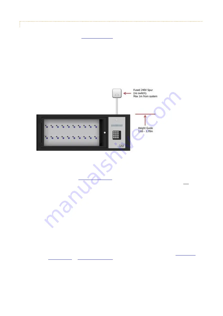
Locate the system on the wall where you want it to go. As a guide the top of the system should be 1.65 –
1.70 meters from the floor and should no further than 1 meter from the mains spur.
2.
Mark and drill the four fixing holes and attach the system to the wall using the appropriate fixings.
3.
20mm knockout holes are provided in the top and bottom of the cabinet. The power supply and
communication cables should be brought to the top or the bottom of the system via 20mm trunking.
NOTE:
section for the power supply connection details and
the relevant communication installation section for the communications connection. Do not switch
on the system at this point.
4.
Once securely fixed to the wall and the mains and communications cables have been run to the system, the
items removed for installation can be replaced.
5.
Replace the 16bit Control PCB Plate or 8bit Control PCB (depending on your system type) and reconnect the
following cables.
Door Lock Cable
Power Cable
Receptor Cable
Comms cable (such as network or RS232 etc.)
NOTE:
For more details on the various PCB connections, please refer to the
section of the Traka32 Help Guide.
6.
Replace all the receptor strips reconnecting the receptor ribbon cable. Using a large flat bladed screwdriver,
secure the receptor strips in place with the fixings and removed earlier.
NOTE:
It is essential that the receptor strips are replaced in the same location from which they
were removed otherwise the system will not function correctly.


