


Parameters
(A) Application parameters
FR-F800
5 - 377
Parameter setting for each PID gain tuning method
Set the following parameters according to the selected tuning method (step response method / limit
cycle method).
Execution of PID gain tuning (Pr. 1219, PGT signal)
●
While the PID gain tuning function is enabled (Pr.1218
≠
"0"), PID gain tuning is started when any
of the following operations is performed during PID control.
–
Turning ON the PID gain tuning start/forced end signal (PGT).
–
Setting Pr.1219 "PID gain tuning start/status" = "1".
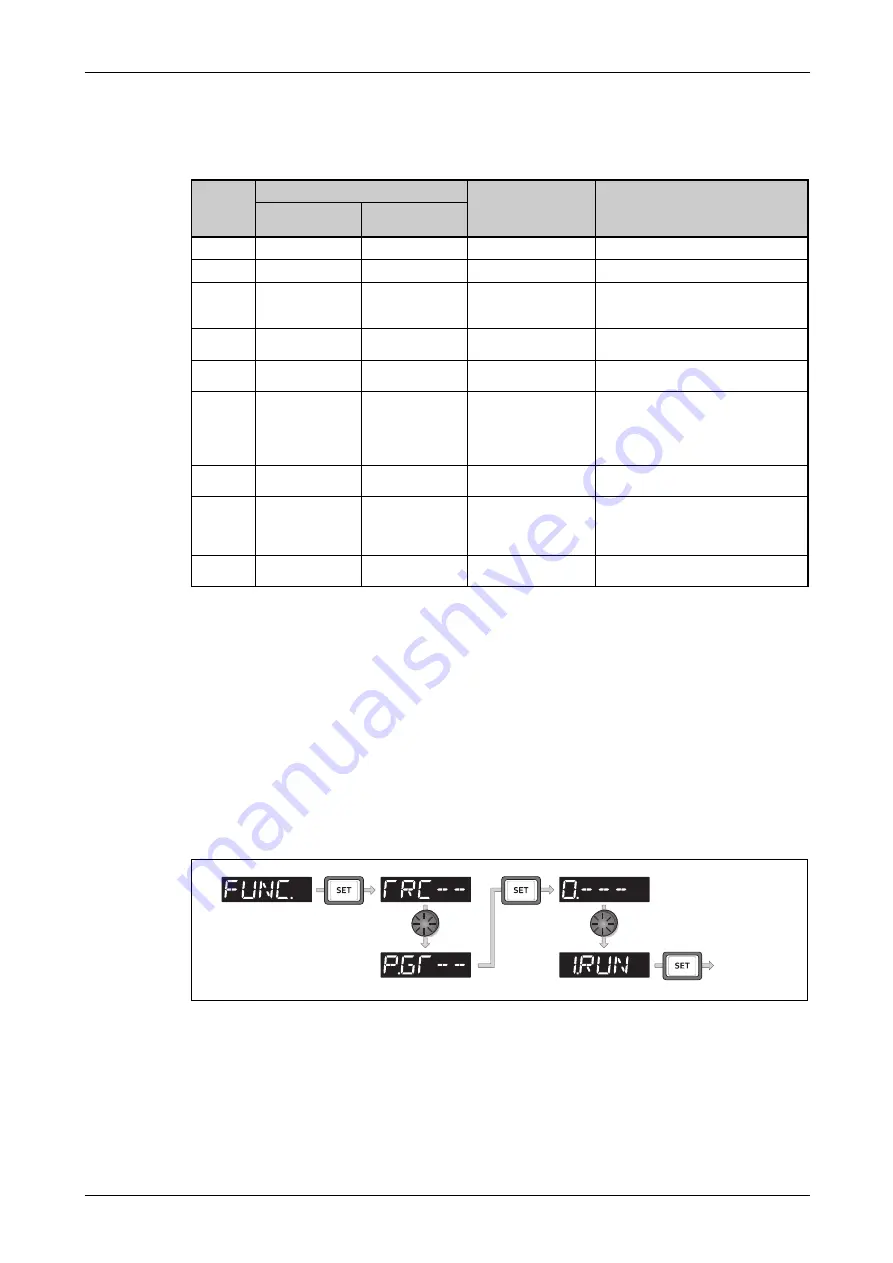
–
Selecting the PID gain tuning start (1.RUN) in the function menu on the operation panel (FR-
DU08).
●
To use the PGT signal, set "81" in any of Pr. 178 to Pr. 189 (input terminal function selection) to
assign the function to an input terminal.
Pr.
Tuning method
Item
Description
Step response
method
Limit cycle
method
128 (753)
PID action selection
Select the PID action.
1218
PID gain tuning setting
Select the PID gain tuning operation.
1211
PID gain tuning
timeout time
Set the timeout time for PID gain tuning.
A timeout error occurs when the elapsed
time exceeds the setting.
1212
—
Step manipulated
amount
Set the step manipulated amount for PID
gain tuning.
1213
—
Step response
sampling cycle
Set the cycle for sampling of
measurement values for PID gain tuning.
1214
—
Timeout time after the
maximum slope
Set the timeout time after the maximum
slope measurement for PID gain tuning.
The measurement for tuning is
completed when the elapsed time
exceeds the setting.
1215
—
Limit cycle output
upper limit
Set the upper limit value of the two-
position output for PID gain tuning.
1216
—
Limit cycle output
lower limit
Set the lower limit value of the two-
position output for PID gain tuning.
(When the setting exceeds the Pr.1215
setting, a tuning error occurs.)
1217
—
Limit cycle hysteresis
Set the hysteresis of the set point for PID
gain tuning.
: Parameter to set
Tab. 5-182:
Parameter setting for each PID gain tuning method
I003046E
Fig. 5-177:
Selection of PID gain tuning start
Tuning start
Summary of Contents for FR-F820-00046
Page 2: ......
Page 4: ......
Page 114: ...System configuration for Ethernet communication FR F800 E Installation and wiring 2 86 ...
Page 172: ...Basic operation procedure JOG operation Basic operation 4 32 ...
Page 812: ...Inverter to inverter link function FR F800 E Parameters 5 640 ...
Page 900: ...Outline dimension drawings Specifications 8 26 ...
Page 929: ...Appendix EC Declarations of Conformity FR F800 A 29 ...
Page 930: ...EC Declarations of Conformity Appendix A 30 ...
Page 931: ...Appendix EC Declarations of Conformity FR F800 A 31 ...
Page 932: ...EC Declarations of Conformity Appendix A 32 ...
Page 933: ...Appendix EC Declarations of Conformity FR F800 A 33 ...
Page 934: ...EC Declarations of Conformity Appendix A 34 ...
Page 935: ...Appendix EC Declarations of Conformity FR F800 A 35 ...
Page 936: ...EC Declarations of Conformity Appendix A 36 ...
Page 937: ...Appendix EC Declarations of Conformity FR F800 A 37 ...
Page 938: ...EC Declarations of Conformity Appendix A 38 ...
Page 939: ......


