


(A) Application parameters
Parameters
5 - 372
Classification
First PID function parameters
Second PID function parameters
Signal
Name
Signal
Name
Input signal
X14
PID control valid terminal
X80
Second PID control valid terminal
X64
During retry
X79
Second PID forward/reverse action
switchover
X72
PID P control switchover
X73
Second PID P control switchover
Output signal
FUP
PID upper limit
FUP2
Second PID upper limit
FDN
PID lower limit
FDN2
Second PID lower limit
RL
PID forward/reverse rotation
output
RL2
Second PID forward/reverse rotation
output
PID
During PID control activated
PID2
Second During PID control activated
SLEEP
PID output interruption
SLEEP2
During second PID output shutoff
Y48
PID deviation limit
Y205
Second PID deviation limit
Tab. 5-179:
I/O signals for setting multiple PID functions
NOTES
Even if the X14 signal is ON, PID control is stopped and multi-speed or JOG operation is performed
when the RH, RM, RL, or REX signal (multi-speed operation) or JOG signal (JOG operation) is input.
PID control is invalid under the following settings.
Pr. 79 "Operation mode selection" = "6" (Switchover mode)
Note that input to the terminal 1 is added to the terminals 2 and 4 inputs. For example when
Pr. 128 = "20 or 21", the terminal 1 input is considered as a set point and added to the set point of
the terminal 2.
To use terminal 4 and 1 inputs in PID control, set "0" (initial value) to Pr. 858 "Terminal 4 function
assignment" and Pr. 868 "Terminal 1 function assignment". When a value other than "0", PID con-
trol is invalid.
Changing the terminal assignment using Pr. 178 to Pr. 189 or Pr. 190 to Pr. 196 may affect other
functions. Set parameters after confirming the function of each terminal.
When PID control is selected, the minimum frequency becomes the frequency of Pr. 902 and the
maximum frequency becomes the frequency of Pr. 903.
(The Pr. 1 "Maximum frequency" and Pr. 2 "Minimum frequency" settings also are valid.)
During PID operation, the remote operation function is invalid.
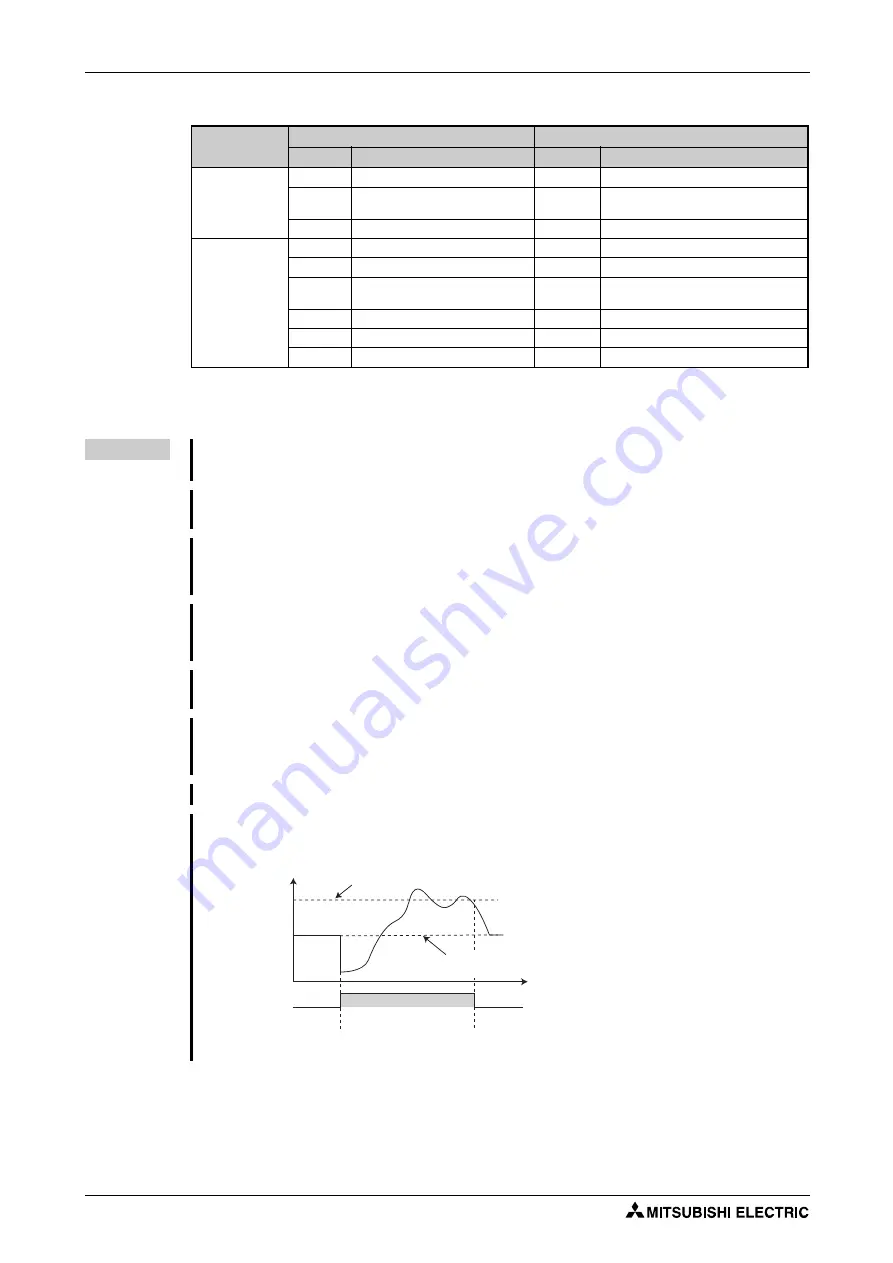
When control is switched to PID control during normal operation, the frequency during that oper-
ation is not carried over, and the value resulting from PID calculation referenced to 0 Hz becomes
the command frequency.
PID set point
Frequency command
during normal operation
Normal operation
PID operation
ON
Frequency
command
PID action
Normal operation
Operation when control is switched to PID control during normal operatio
Summary of Contents for FR-F820-00046
Page 2: ......
Page 4: ......
Page 114: ...System configuration for Ethernet communication FR F800 E Installation and wiring 2 86 ...
Page 172: ...Basic operation procedure JOG operation Basic operation 4 32 ...
Page 812: ...Inverter to inverter link function FR F800 E Parameters 5 640 ...
Page 900: ...Outline dimension drawings Specifications 8 26 ...
Page 929: ...Appendix EC Declarations of Conformity FR F800 A 29 ...
Page 930: ...EC Declarations of Conformity Appendix A 30 ...
Page 931: ...Appendix EC Declarations of Conformity FR F800 A 31 ...
Page 932: ...EC Declarations of Conformity Appendix A 32 ...
Page 933: ...Appendix EC Declarations of Conformity FR F800 A 33 ...
Page 934: ...EC Declarations of Conformity Appendix A 34 ...
Page 935: ...Appendix EC Declarations of Conformity FR F800 A 35 ...
Page 936: ...EC Declarations of Conformity Appendix A 36 ...
Page 937: ...Appendix EC Declarations of Conformity FR F800 A 37 ...
Page 938: ...EC Declarations of Conformity Appendix A 38 ...
Page 939: ......


