


Parameters
Speed control under PM motor control
FR-F800
5 - 55
5.3.2 Performing
high-accuracy,
fast-response control (gain adjustment for PM
motor control)
Manual gain adjustment is useful for achieving optimum machine performance or improving unfa-
vorable conditions, such as vibration and acoustic noise during operation with high load inertia or
gear backlash.
NOTES
To change to the PM motor control, perform PM parameter initialization at first. If parameter ini-
tialization is performed after setting other parameters, some of those parameters will be initialized
too. (Refer to page 5-51 for the parameters that are initialized.)
Constant-speed operation cannot be performed in the low-speed range of 150 r/min or less.
During PM motor control, the RUN signal is output about 100 ms after turning ON the start com-
mand (STF, STR). The delay is due to the magnetic pole detection.
During PM motor control, the automatic restart after instantaneous power failure function oper-
ates only when an MM-EFS or MM-THE4 IPM motor is connected.
When a regeneration unit is used, the frequency search may not be available if the rotation speed
is about 10% higher than the rated speed.
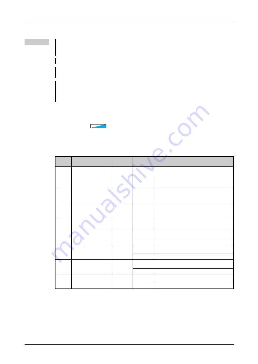
Pr.
Name
Initial
value
Setting
range
Description
820
G211
Speed control P gain 1
25%
0 to 1000%
The proportional gain during speed control is set.
(Setting this parameter higher improves the
trackability for speed command changes. It also
reduces the speed fluctuation caused by external
disturbance.)
821
G212
Speed control integral time
1
0.333 s
0 to 20 s
The integral time during speed control is set. (Setting
this parameter lower shortens the return time to the
original speed when the speed fluctuates due to
external disturbance.)
824
G213
Torque control P gain 1
(current loop proportional
gain)
50%
0 to 500%
The proportional gain of the current controller is set.
825
G214
Torque control integral
time 1 (current loop
integral time)
40 ms
0 to 500 ms
The integral time of the current controller is set.
830
G311
Speed control P gain 2
9999
0 to 1000%
Second function of Pr. 820 (valid when RT signal is
ON)
9999
The Pr. 820 setting is applied to the operation.
831
G312
Speed control integral time
2
9999
0 to 20 s
Second function of Pr. 821 (valid when RT signal is
ON)
9999
The Pr. 821 setting is applied to the operation.
834
G313
Torque control P gain 2
9999
0 to 500%
Second function of Pr. 824 (valid when RT signal is
ON)
9999
The Pr. 824 setting is applied to the operation.
835
G314
Torque control integral
time 2
9999
0 to 500 s
Second function of Pr. 825 (valid when RT signal is
ON)
9999
The Pr. 825 setting is applied to the operation.
PM
PM
PM
Summary of Contents for FR-F820-00046
Page 2: ......
Page 4: ......
Page 114: ...System configuration for Ethernet communication FR F800 E Installation and wiring 2 86 ...
Page 172: ...Basic operation procedure JOG operation Basic operation 4 32 ...
Page 812: ...Inverter to inverter link function FR F800 E Parameters 5 640 ...
Page 900: ...Outline dimension drawings Specifications 8 26 ...
Page 929: ...Appendix EC Declarations of Conformity FR F800 A 29 ...
Page 930: ...EC Declarations of Conformity Appendix A 30 ...
Page 931: ...Appendix EC Declarations of Conformity FR F800 A 31 ...
Page 932: ...EC Declarations of Conformity Appendix A 32 ...
Page 933: ...Appendix EC Declarations of Conformity FR F800 A 33 ...
Page 934: ...EC Declarations of Conformity Appendix A 34 ...
Page 935: ...Appendix EC Declarations of Conformity FR F800 A 35 ...
Page 936: ...EC Declarations of Conformity Appendix A 36 ...
Page 937: ...Appendix EC Declarations of Conformity FR F800 A 37 ...
Page 938: ...EC Declarations of Conformity Appendix A 38 ...
Page 939: ......


