


(A) Application parameters
Parameters
5 - 374
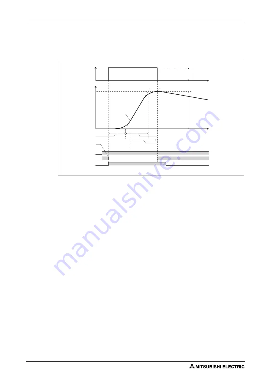
Step response method
●
In the step response method, the manipulated amount is changed step by step for the real system.
From the change in the measured values, the maximum slope (R) and the equivalent waste time
(L) are calculated to determine each constant.
●
The step manipulated amount (Pr. 1212 – 1000) is added to the present manipulated amount.
●
The measured value is taken for every sampling cycle of step response (Pr. 1213). From the
variation between the measured values (Y) and the time (t), the maximum slope (R) is calculated.
●
The measurement ends when the timeout time after the maximum slope (Pr.1214) elapsed after
the maximum slope is obtained.
●
After the integral term is cleared, PID control is performed with the constant to which the change
has been applied (the constant used before PID gain tuning when a fault occurs).
Limit cycle method
●
In the limit cycle method, the two-position ON/OFF operation is performed three times for output
of the manipulated amount for the real system. From the vibration waveform data of the measured
values, the vibration amplitude (Xc) and the vibration cycle (Tc) are measured. Based on the
measured values, each constant is determined.
●
In the limit cycle method, less influence of the noise of the measured values is given as compared
in the step response method, and a stable tuning result can be obtained.
I003044E
Fig. 5-175:
Timing diagram of step response method
Maximum
slope R
(R=Y/T)
Maximum
slope R
(R=Y/T)
STF
PID
PGT
Step manipulated amount
(Pr. 1212 – 1000)
PID gain tuning end
Measured value
variation range Y
Time
Equivalent time constant T (s)
Timeout time after the maximum slope (s)
(Pr.1214)
Manipulated
amount [%]
Measured value
[%]
Equivalent
waste time L (s)
PID gain tuning start
Maximum
slope R
(R = Y/T)
Time
Summary of Contents for FR-F820-00046
Page 2: ......
Page 4: ......
Page 114: ...System configuration for Ethernet communication FR F800 E Installation and wiring 2 86 ...
Page 172: ...Basic operation procedure JOG operation Basic operation 4 32 ...
Page 812: ...Inverter to inverter link function FR F800 E Parameters 5 640 ...
Page 900: ...Outline dimension drawings Specifications 8 26 ...
Page 929: ...Appendix EC Declarations of Conformity FR F800 A 29 ...
Page 930: ...EC Declarations of Conformity Appendix A 30 ...
Page 931: ...Appendix EC Declarations of Conformity FR F800 A 31 ...
Page 932: ...EC Declarations of Conformity Appendix A 32 ...
Page 933: ...Appendix EC Declarations of Conformity FR F800 A 33 ...
Page 934: ...EC Declarations of Conformity Appendix A 34 ...
Page 935: ...Appendix EC Declarations of Conformity FR F800 A 35 ...
Page 936: ...EC Declarations of Conformity Appendix A 36 ...
Page 937: ...Appendix EC Declarations of Conformity FR F800 A 37 ...
Page 938: ...EC Declarations of Conformity Appendix A 38 ...
Page 939: ......


