3. Adjustment of Dog-type Reference Point Return
3.3 Reference Point Return Parameters
III
-13
(7) Reference point return direction (#2030 dir (
−
))
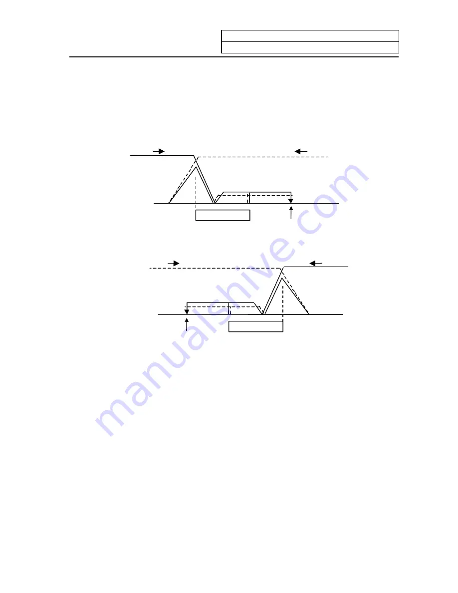
This parameter sets the direction to move after the limit switch kicks the dog causing a deceleration
stop during dog-type reference point return. The direction is either positive "0" or negative "1".
If the reference point position is in the positive direction from the near-point dog, set "0".
If the reference point position is in the negative direction from the near-point dog, set "1".
(a) When reference point return direction is positive (+)
(–)
(+)
To move in
+ direction
To move in
−
direction
Dog
Reference point
(b) When reference point return direction is negative (
−
)
(–)
(+)
To move in
+ direction
To move in
−
direction
Dog
Reference point
(8) Axis with no reference point (#2031 noref)
"0" is set for the axis to carry out dog-type reference point return and the axis for absolute position
detection.
"1" is set for the axis that does not carry out reference point return during relative position
detection.
(9) Machine coordinate system offset (#2037 G53ofs)
This parameter is set when the basic machine coordinate system zero point position is to be
shifted from the reference point position.
When "0" is set, the reference point position will be the position of the basic machine coordinate
system zero point.
G53ofs sets the reference point position from the basic machine coordinate system zero point as a
basic machine coordinate system coordinate value. The machine value becomes this value with
reference point return after the power is turned ON, and the basic machine coordinate system is
established.
(10) Grid display selection (#1229 set01/bit6)
Select a grid type to be displayed on the servo monitor screen during dog type reference point
return.
0: Selects the distance between dog OFF and zero point (including a grid mask amount).
1: Selects a value given by reducing a grid mask amount from the distance between dog OFF
and zero point.
Summary of Contents for EZMotion-NC E60 Series
Page 1: ......
Page 15: ...I OPERATION SECTION ...
Page 361: ...II MACHINE OPERATION MANUAL ...
Page 399: ...III SETUP ...
Page 472: ...IV APPENDIXES ...
Page 510: ......


