312
Learning Advanced Features
Outputs a signal when communication power is
present and an I/O expansion card is installed. It also
outputs a signal when losing analog input and
communication power commands.
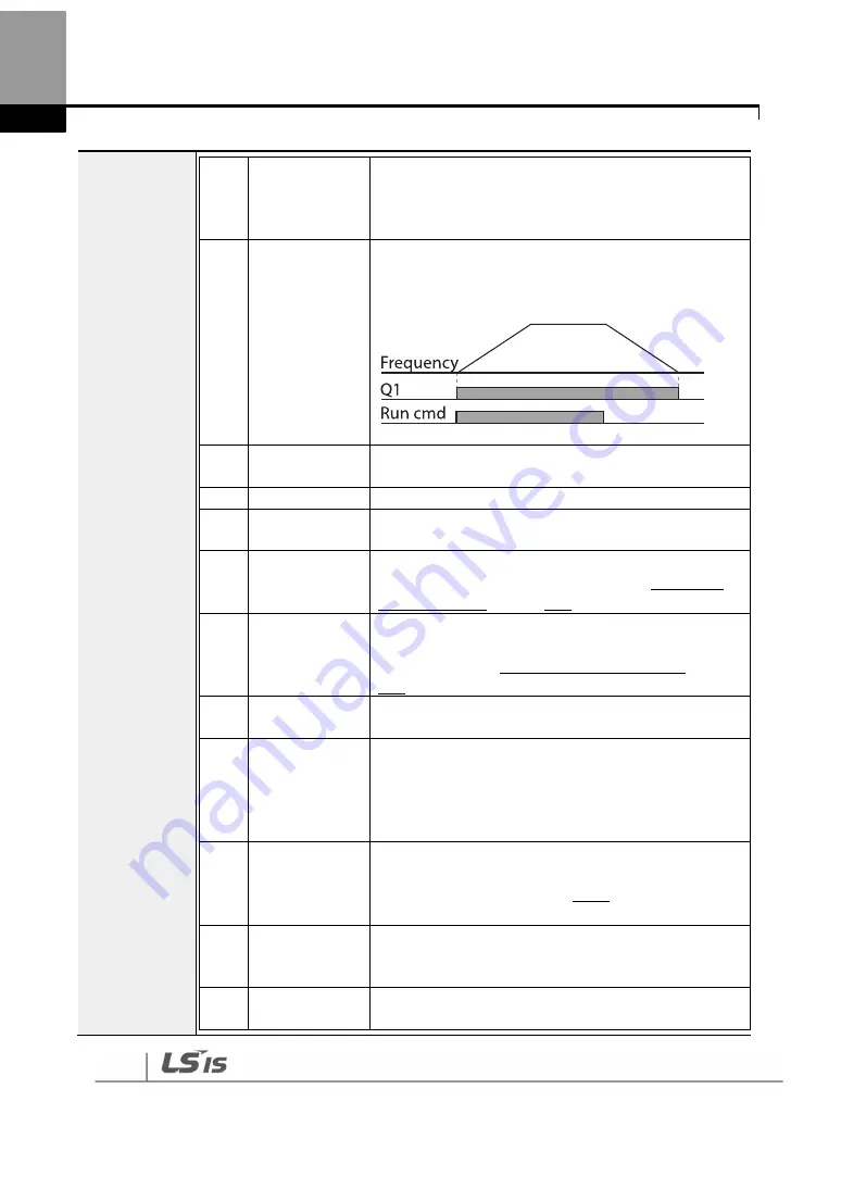
14
RUN
Outputs a signal when an operation command is
entered and the inverter outputs voltage.
No signal output during DC braking.
15
Stop
Outputs a signal at operation command off, and when
there is no inverter output voltage.
16
Steady
Outputs a signal in steady operation.
17
Inverter Line
Outputs a signal while the motor is driven by the
inverter line.
18
Comm Line
Outputs a signal when multi-function input terminal
(switching) is entered. For details, refer to
5.31Supply
Power Transition
page on
253.
19
Speed Search
Outputs a signal during inverter speed search
operation.
For details, refer to
5.27Speed Search Operation
on page
243.
20
Ready
Outputs a signal when the inverter is in stand by mode
and ready to receive external operation commands.
21
MMC
Used as a multi-motor control function. By configuring
the relay output and the multi-function output to
MMC and configuring the AP1-40–AP1-92, it can
conduct the necessary operations for multi-motor
control function.
22
Timer Out
A timer function to operate terminal output after a
certain time by using multi-function terminal block
input. For details, refer to 5.43
Timer
Settings
on page
265.
23
Trip
Outputs a signal after a fault trip.
Refer to 5.45 Multi-function Output On/Off Control on
page 259 .
25
DB Warn %ED Refer to 0. Dynamic Braking (DB) Resistor
Configuration on page 295.
Summary of Contents for 6731001500
Page 1: ......
Page 17: ...Preparing the Installation 4 37 90kW 3 Phase ...
Page 18: ...Preparing the Installation 5 110 132kW 3 Phase ...
Page 19: ...Preparing the Installation 6 160 185kW 3 Phase ...
Page 20: ...Preparing the Installation 7 220 250kW 3 Phase ...
Page 21: ...Preparing the Installation 8 315 400kW 3 Phase ...
Page 22: ...Preparing the Installation 9 500kW 3 Phase ...
Page 34: ...21 Installing the Inverter 400 V 220 500kW ...
Page 50: ...37 Installing the Inverter Inputand OutputControlTerminalBlockWiringDiagram 5 5 90kW ...
Page 66: ...Perform BasicOperations 53 ...
Page 106: ...93 Learning BasicFeatures 0 10V InputVoltageSettingDetails V1 Quantizing ...
Page 107: ...94 Learning BasicFeatures ...
Page 187: ...174 Learning Advanced Features PIDCommandBlock ...
Page 188: ...175 Learning Advanced Features ...
Page 189: ...176 Learning Advanced Features PIDFeedbackBlock ...
Page 190: ...177 Learning Advanced Features PIDOutputBlock ...
Page 191: ...178 Learning Advanced Features PIDOutputModeBlock ...
Page 205: ...192 Learning Advanced Features EPID1Controlblock ...
Page 206: ...193 Learning Advanced Features EPID2Controlblock ...
Page 228: ...215 Learning Advanced Features ...
Page 244: ...231 Learning Advanced Features TheTime Chartfor the Exception Day ...
Page 260: ...247 Learning Advanced Features SpeedSearchOperation SettingDetails ...
Page 405: ...392 RS 485 Communication Features 7 3 9 2 Control Area Parameter Read Write ...
Page 555: ...Table ofFunctions 542 8 16 4 CoolingTower MC4 Group ...
Page 558: ...Tableof Functions 545 8 16 5 Circulation Pump MC5 Group ...
Page 562: ...Tableof Functions 549 8 16 6 Vacuum Pump MC6 Group ...
Page 588: ...575 Troubleshooting ...
Page 608: ...TechnicalSpecification 595 11 3 External Dimensions 0 75 30kW 3 phase 37 90kW 3 phase ...
Page 609: ...TechnicalSpecification 596 110 185kW 3 phase ...
Page 632: ...TechnicalSpecification 619 400 V 37 500 kW Current Derating Rate ...
Page 643: ...630 ...
Page 644: ...631 ...
Page 645: ...632 ...


