145
Learning Advanced Features
5
Learning Advanced Features
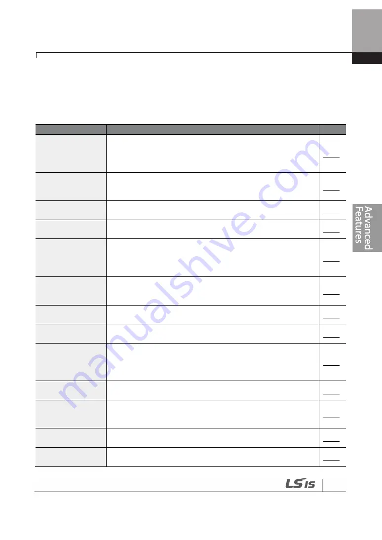
This chapter describes the advanced features of the H100 inverter. Check the reference page in the
table to see the detailed description for each of the advanced features.
Advanced Tasks
Description
Ref.
Auxiliary frequency
operation
Use the main and auxiliary frequencies in the predefined formulas
to create various operating conditions. Auxiliary frequency
operation is ideal for Draw Operation* as this feature enables fine-
tuning of operation speeds.
p.147
Jog operation
Jog operation is a kind of a manual operation. The inverter operates
to a set of parameter settings predefined for Jog operation while
the Jog command button is pressed.
p.153
Up-down operation
Uses the upper and lower limit value switch output signals (i.e.
signals from a flow meter) as Acc/Dec commands to motors.
p.155
3-wire operation
3-wire operation is used to latch an input signal. This configuration
is used to operate the inverter by a push button.
p.157
Safety operation
mode
This safety feature allows the inverter’s operation only after a signal
is input to the multi-function terminal designated for the safety
operation mode. This feature is useful when extra care is needed in
operating the inverter using the multi-purpose terminals.
p.158
Dwell operation
Use this feature for the lift-type loads such as elevators, when the
torque needs to be maintained while the brakes are applied or
released.
p.160
Slip compensation
This feature ensures that the motor rotates at a constant speed, by
compensating for the motor slip as a load increases.
p.162
PID control
PID control provides constant automated control of flow, pressure,
and temperature by adjusting the output frequency of the inverter.
p.163
Sleep-wakeup
operation
When the inverter operation continues below the PID conditions
for a set time period, the PID reference is automatically raised to
extend the operation standby time. This keeps the inverter in a
standby (sleep) mode when the demand is very low.
p.180
Auto-tuning
Used to automatically measure the motor control parameters to
optimize the inverter’s control mode performance.
p.219
Energy buffering
operation
Used to maintain the DC link voltage for as long as possible by
controlling the inverter output frequency during power
interruptions, thus to delay a low voltage fault trip.
p.197
Energy saving
operation
Used to save energy by reducing the voltage supplied to motors
during low-load and no-load conditions.
p.239
Speed search
operation
Used to prevent fault trips when the inverter voltage is output while
the motor is idling or free-running.
p.243
Summary of Contents for 6731001500
Page 1: ......
Page 17: ...Preparing the Installation 4 37 90kW 3 Phase ...
Page 18: ...Preparing the Installation 5 110 132kW 3 Phase ...
Page 19: ...Preparing the Installation 6 160 185kW 3 Phase ...
Page 20: ...Preparing the Installation 7 220 250kW 3 Phase ...
Page 21: ...Preparing the Installation 8 315 400kW 3 Phase ...
Page 22: ...Preparing the Installation 9 500kW 3 Phase ...
Page 34: ...21 Installing the Inverter 400 V 220 500kW ...
Page 50: ...37 Installing the Inverter Inputand OutputControlTerminalBlockWiringDiagram 5 5 90kW ...
Page 66: ...Perform BasicOperations 53 ...
Page 106: ...93 Learning BasicFeatures 0 10V InputVoltageSettingDetails V1 Quantizing ...
Page 107: ...94 Learning BasicFeatures ...
Page 187: ...174 Learning Advanced Features PIDCommandBlock ...
Page 188: ...175 Learning Advanced Features ...
Page 189: ...176 Learning Advanced Features PIDFeedbackBlock ...
Page 190: ...177 Learning Advanced Features PIDOutputBlock ...
Page 191: ...178 Learning Advanced Features PIDOutputModeBlock ...
Page 205: ...192 Learning Advanced Features EPID1Controlblock ...
Page 206: ...193 Learning Advanced Features EPID2Controlblock ...
Page 228: ...215 Learning Advanced Features ...
Page 244: ...231 Learning Advanced Features TheTime Chartfor the Exception Day ...
Page 260: ...247 Learning Advanced Features SpeedSearchOperation SettingDetails ...
Page 405: ...392 RS 485 Communication Features 7 3 9 2 Control Area Parameter Read Write ...
Page 555: ...Table ofFunctions 542 8 16 4 CoolingTower MC4 Group ...
Page 558: ...Tableof Functions 545 8 16 5 Circulation Pump MC5 Group ...
Page 562: ...Tableof Functions 549 8 16 6 Vacuum Pump MC6 Group ...
Page 588: ...575 Troubleshooting ...
Page 608: ...TechnicalSpecification 595 11 3 External Dimensions 0 75 30kW 3 phase 37 90kW 3 phase ...
Page 609: ...TechnicalSpecification 596 110 185kW 3 phase ...
Page 632: ...TechnicalSpecification 619 400 V 37 500 kW Current Derating Rate ...
Page 643: ...630 ...
Page 644: ...631 ...
Page 645: ...632 ...


