8-1
January 24, 2017
Electrical System
CLG835H
Electrical System
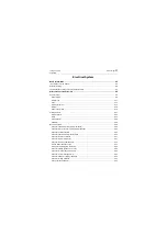
Instructions of service manual ...............................................................................................................8-5
Notes for welding ...................................................................................................................................8-5
The introduction of signs on the electrical schematic.............................................................................8-7
Power System ....................................................................................................................................8-9
Electric lock .....................................................................................................................................8-11
Fuse .................................................................................................................................................8-12
Disconnect switch ............................................................................................................................8-15
Battery..............................................................................................................................................8-16
Power supply relay...........................................................................................................................8-18
Start Contactor .................................................................................................................................8-24
Relay ................................................................................................................................................8-24
Starting Motor...................................................................................................................................8-25
Alternator..........................................................................................................................................8-26
Circuit for engine water temperature indication................................................................................8-28
Circuit for torque converter oil temperature indication .....................................................................8-28
Circuit for oil pressure alarm ............................................................................................................8-30
Circuit for transmission oil pressure alarm .......................................................................................8-30
Circuit for fuel level indication ..........................................................................................................8-31
Circuit for DEF level indication .........................................................................................................8-33
Circuit for vehicle speed indication...................................................................................................8-33
Service brake indication circuit.........................................................................................................8-33
Wiring schematic diagram of braking ...............................................................................................8-34
Circuit for parking brake power cut-off .............................................................................................8-36
Circuit for service brake clutch on/off ...............................................................................................8-39
Circuit for air filter blockage alarm....................................................................................................8-40
Circuit for alternator charging indication...........................................................................................8-40
Circuit for voltage indication .............................................................................................................8-42
Circuit of preheat indicator ...............................................................................................................8-43
Summary of Contents for CLG835H
Page 2: ......
Page 4: ...Contents January 24 2017 CLG835H...
Page 6: ...1 2 General Information January 24 2017 CLG835H...
Page 38: ...1 34 Machine Inspection Table January 24 2017 CLG835H...
Page 156: ...3 2 Power Train System January 24 2017 CLG835H...
Page 214: ...3 2 Power Train System January 24 2017 CLG835H...
Page 272: ...3 60 Testing and adjustment January 24 2017 Power Train Test CLG835H...
Page 276: ...4 4 Hydraulic System January 24 2017 CLG835H...
Page 552: ...6 2 Driver s Cab System January 24 2017 CLG835H...
Page 608: ...7 2 Structure January 24 2017 CLG835H...
Page 662: ...8 4 Electrical System January 24 2017 CLG835H...
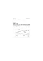
Page 677: ...8 19 January 24 2017 Structure Function Principle CLG835H Power System P18E00014...


