3-52
Removal and Installation
January 24, 2017
Removal and installation of rear axle assembly
CLG835H
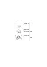
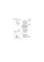
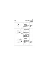
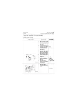
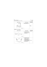
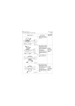
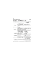
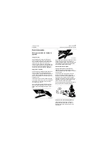
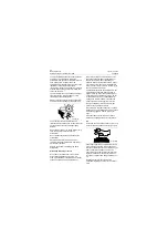
7. Install thrust washer and
pressing plate and align the
holes well.
8. Apply thread lock sealant to
thread portion of bolt, screw
bolts and hard washers into
the clamping plate thread
holes by 2-3 teeth by hand,
and drive them in
symmetrically with
pneumatic impact wrench
with the tightening torque of
305±25Nm\ 224.94±18.44
lbf•ft.
24# socket,
pneumatic
impact wrench,
open-end 24#
fixed torque
spanner
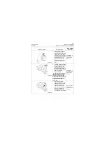
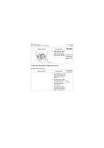
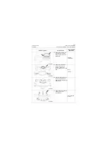
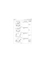
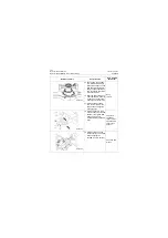
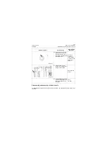
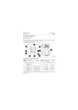
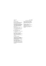
9. Put a thrust washer and
cover and align the holes
well.
10. Apply thread lock sealant to
thread of bolts, screw bolts
and hard washers into cover
thread holes by 2-3 teeth by
hand, and drive them in
symmetrically with
pneumatic impact wrench
with the tightening torque of
195±15Nm\ 143.81±11.06
lbf•ft.
21# socket,
pneumatic
impact wrench,
open-end 21#
fixed torque
spanner
Reference picture
Operation step
Tools required
(Remarks)
P18T00110
P18T00111
P18T00112
P18T00113
Summary of Contents for CLG835H
Page 2: ......
Page 4: ...Contents January 24 2017 CLG835H...
Page 6: ...1 2 General Information January 24 2017 CLG835H...
Page 38: ...1 34 Machine Inspection Table January 24 2017 CLG835H...
Page 156: ...3 2 Power Train System January 24 2017 CLG835H...
Page 214: ...3 2 Power Train System January 24 2017 CLG835H...
Page 272: ...3 60 Testing and adjustment January 24 2017 Power Train Test CLG835H...
Page 276: ...4 4 Hydraulic System January 24 2017 CLG835H...
Page 552: ...6 2 Driver s Cab System January 24 2017 CLG835H...
Page 608: ...7 2 Structure January 24 2017 CLG835H...
Page 662: ...8 4 Electrical System January 24 2017 CLG835H...
Page 677: ...8 19 January 24 2017 Structure Function Principle CLG835H Power System P18E00014...

