4-107
January 24, 2017
Removal and Installation
CLG835H
Work hydraulic system
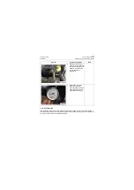
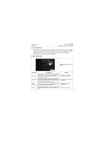
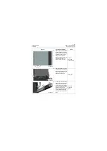
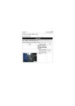
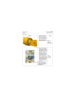
2. Find the drain plug at bottom
of right oil tank at rear frame,
and then wipe clean the cir-
cumference of drain plug;
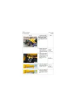
3. Place a clean oil basin
below the drain plug for col-
lecting the hydraulic oil;
screw off the drain plug;
Oil basin;
Open-end
wrench: 30mm
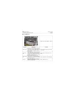
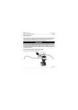
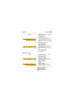
4. After the hydraulic oil in the
hydraulic oil tank is drained,
hang the lug welded on both
sides of the hydraulic oil
tank with a lifting rope;
Lifting rope
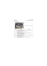
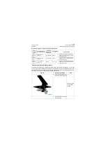
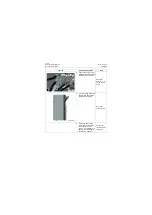
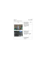
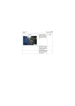
5. Loosen the oil suction hose
clamp of the plunger pump
and gear pump located at
lower part of back of oil tank,
remove the oil suction hose
and mask the oil ports;
remove the oil suction hose
joint of secondary steering
pump (option) and mask oil
ports.
Open-end
wrench: 8,
36mm;
Figures
Operation instruction
Tools
P18H00122
P18H00123
P18H00124
Summary of Contents for CLG835H
Page 2: ......
Page 4: ...Contents January 24 2017 CLG835H...
Page 6: ...1 2 General Information January 24 2017 CLG835H...
Page 38: ...1 34 Machine Inspection Table January 24 2017 CLG835H...
Page 156: ...3 2 Power Train System January 24 2017 CLG835H...
Page 214: ...3 2 Power Train System January 24 2017 CLG835H...
Page 272: ...3 60 Testing and adjustment January 24 2017 Power Train Test CLG835H...
Page 276: ...4 4 Hydraulic System January 24 2017 CLG835H...
Page 552: ...6 2 Driver s Cab System January 24 2017 CLG835H...
Page 608: ...7 2 Structure January 24 2017 CLG835H...
Page 662: ...8 4 Electrical System January 24 2017 CLG835H...
Page 677: ...8 19 January 24 2017 Structure Function Principle CLG835H Power System P18E00014...


