5-19
January 24, 2017
Removal and Installation
CLG835H
Removal and installation of A/C components
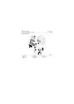
Removal and installation of evaporator mounting assembly
The following operation sequence is used for removing evaporator as from cab as. Most actual
failures are failures of certain components (such as fan, circuit, etc.) in evaporator, so it is sug-
gested to carry out selective removal, repair and replacement after failure judgment in Chapter
Fault Diagnosis and Judgment of this manual in order to avoid unnecessary operations.
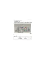
Figures
Removal and installation
Tools
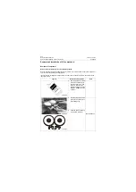
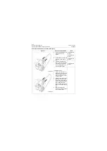
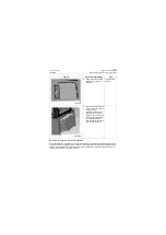
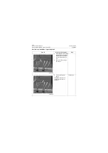
1. Drain refrigerant in air condi-
tioning system as required in
Release (recover) refriger-
ant in air conditioning sys-
tem.
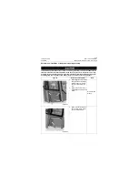
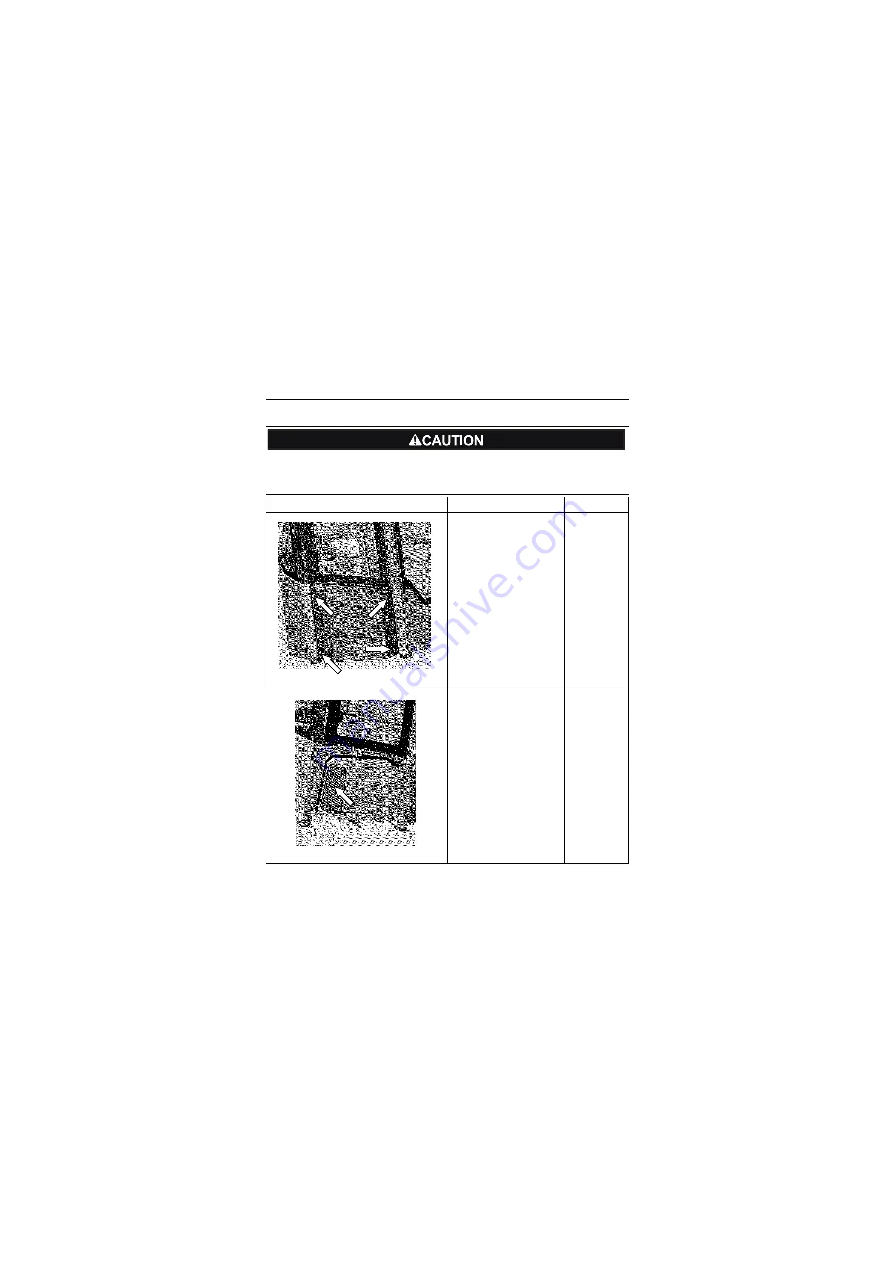
2. Remove the cab-rh cover (
install flange bolt whose bolt
is M8)
#13 Open-end
wrench
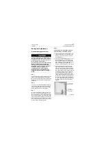
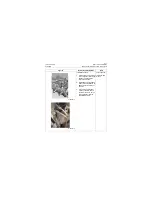
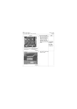
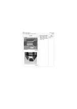
3. Remove the left evaporator
fresh air filter which is fixed
by three butterfly bolts.
P18A00017
P18A00018
Summary of Contents for CLG835H
Page 2: ......
Page 4: ...Contents January 24 2017 CLG835H...
Page 6: ...1 2 General Information January 24 2017 CLG835H...
Page 38: ...1 34 Machine Inspection Table January 24 2017 CLG835H...
Page 156: ...3 2 Power Train System January 24 2017 CLG835H...
Page 214: ...3 2 Power Train System January 24 2017 CLG835H...
Page 272: ...3 60 Testing and adjustment January 24 2017 Power Train Test CLG835H...
Page 276: ...4 4 Hydraulic System January 24 2017 CLG835H...
Page 552: ...6 2 Driver s Cab System January 24 2017 CLG835H...
Page 608: ...7 2 Structure January 24 2017 CLG835H...
Page 662: ...8 4 Electrical System January 24 2017 CLG835H...
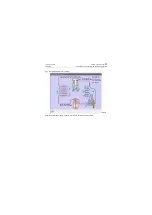
Page 677: ...8 19 January 24 2017 Structure Function Principle CLG835H Power System P18E00014...

