4-48
Structure Function Principle
January 24, 2017
Brake system
CLG835H
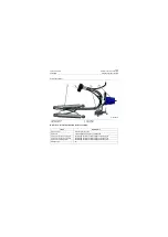
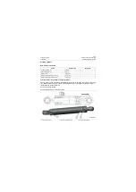
Overview - technical parameters of brake
system
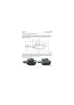
Overview - working principle of brake system
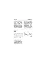
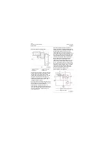
Working principle of full-hydraulic brake: the
system pressure is kept by accumulator
assembly and each brake circuit is equipped with
accumulator independently. When oil pressure in
the accumulator is lower than the setting
minimum working pressure of the system (the
pressure for CLG835H_T4f is
\1957.5psi), the
charge valve feeds the pressure oil of brake
pump (CLG835H_T4f brake pump and cooling
pump form tandem pump and share one pump
body) filtered and outputted by oil filter into the
accumulator. When oil pressure in the
accumulator reaches the setting maximum
working pressure (the pressure for
CLG835H_T4f is 16MPa\2320psi), the charge
valve stops supplying oil for the accumulator of
brake system. The brake pump is unloaded by
connecting S port of charge valve with oil tank. At
the time of braking, depress the brake valve
pedal, high pressure oil stored in the
accumulator of service brake circuit enters into
the axle via the service brake valve so as to push
the brake piston in the axle, the piston compacts
the wet-type friction plate and half shaft of wet-
type brake axle to realize the service brake of the
complete machine. After releasing the brake
pedal and removing brake, oil in the axle returns
to oil tank via the brake valve.
When applying the parking brake, emergency &
parking brake system controls the brake valve
block assembly using the parking brake solenoid
valve switch in the cab to make the parking brake
accumulator release pressure oil which controls
the brake cylinder to realize emergency &
parking brake function. In addition, the pressure
control switch in electrical system can also
realize the complete machine brake.
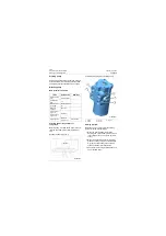
Power cut-off function (i.e. function of brake and
spontaneous out-of-gear): when the shift control
lever is in forward or backward I & II position and
the clutch on/off switch is closed (i.e. push button
lamp is on) during driving, once apply the foot
brake, electric control box sends a command to
the shift control valve to engage the transmission
in N position and cut off power. When the shift
control lever is in forward or backward I & II
position and the clutch on/off switch is
disconnected (i.e. push button lamp is off) during
driving, once the brake is applied, the power will
not be cut off.
Clutch on/off switch is a switch with self-locking
function, refer to the electrical system in the
manual for detail of using method.
The "function of brake and spontaneous out-of-
gear" can work only in forward or backward I & II
position. In order to guarantee safe driving, when
load is in high-speed position, once the brake is
applied, the electric control box will not sends the
command of cutting off power no matter whether
the clutch on/off switch is closed or
disconnected, which is determined by driving
properties of the loader.
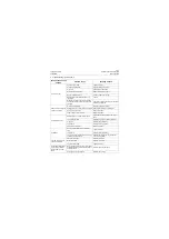
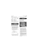
Items
Parameters
Service brake system
Dual-circuit full-hydraulic wet
brake
Parking brake system
Electronically controlled full
hydraulic brake
Pressure of brake
pump relief valve
18±0.5MPa\2610±72.5psi
Output pressure of
brake valve
6±0.4MPa\870±58psi
System flow
30L/min@2200r/min\7.93US
gpm@2200rpm
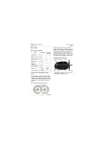
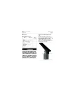
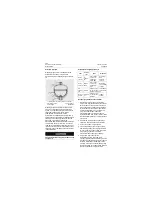
Emergency brake button and clutch on/off switch
1. Emergency Brake Button
2. Clutch on/off sw
P18H00037
1
2
Summary of Contents for CLG835H
Page 2: ......
Page 4: ...Contents January 24 2017 CLG835H...
Page 6: ...1 2 General Information January 24 2017 CLG835H...
Page 38: ...1 34 Machine Inspection Table January 24 2017 CLG835H...
Page 156: ...3 2 Power Train System January 24 2017 CLG835H...
Page 214: ...3 2 Power Train System January 24 2017 CLG835H...
Page 272: ...3 60 Testing and adjustment January 24 2017 Power Train Test CLG835H...
Page 276: ...4 4 Hydraulic System January 24 2017 CLG835H...
Page 552: ...6 2 Driver s Cab System January 24 2017 CLG835H...
Page 608: ...7 2 Structure January 24 2017 CLG835H...
Page 662: ...8 4 Electrical System January 24 2017 CLG835H...
Page 677: ...8 19 January 24 2017 Structure Function Principle CLG835H Power System P18E00014...


