4-21
January 24, 2017
Structure Function Principle
CLG835H
Work hydraulic system
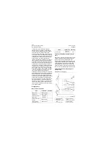
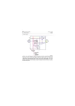
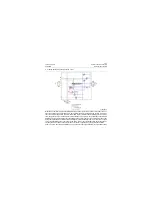
1. Before starting, the pressure of pump open-
ing P=0, the pressure of load sensing port 4
P
LS
=0, the pressure difference between both
ends of control valve 3
Δ
P= P- P
LS
=0 and
the swashplate is in the maximum displace-
ment position.
2. After starting, when the control valve 3 has
no opening, P
LS
=0, the pressure P of pump
opening acts on left end of flow compensator
valve 5, the flow compensator valve 5 moves
rightwards, oil enters big cavity of variable
cylinder 7, the swashplate turns anticlock-
wise and the displacement of pump is
reduced to the minimum. The pressure P of
the pump opening is generally set to 2.6Mpa\
377psi at this time, i.e. the setting pressure of
the flow compensator valve 5, in order to
improve the response speed of the system
and compensate a small amount of leak.
3. When the control valve 3 has an opening to
some extent, P
LS
occurs,
Δ
P starts to
decrease from the maximum value, the flow
compensator valve 5 moves leftwards under
the action of its spring force P
K
. The big cav-
ity of differential variable cylinder 7 returns oil
gradually, the swashplate turns clockwise
and the displacement of pump starts to
increase.
4. When the opening of the control valve 3
increases further, throttling effect fades,
Δ
P
decreases, flow compensator valve 5 moves
leftwards under the action of its spring force
P
K
, the big cavity of differential variable cylin-
der 7 returns oil gradually, the swashplate
turns clockwise and the displacement of
pump starts to increase.
Δ
P is also increased
with the increase of displacement (flow),
when flow of the system is stable,
Δ
P= P
K
=
fixed value, otherwise, balance of the flow
compensator valve 5 will be disturbed.
5. When the opening of the control valve 3
decreases, throttling effect becomes
enhanced,
Δ
P increases, the flow compensa-
tor valve 5 moves rightwards under the action
of
Δ
P, oil enters big cavity of variable cylinder
7, the swashplate turns anticlockwise and the
displacement of pump is reduced to the mini-
mum. When the system is stable,
Δ
P= P
K
=
fixed value.
6. When the load pressure increases up to the
setting pressure value of the system, the
pressure shut-off valve 6 opens the pump
pressure oil way to the big cavity of variable
cylinder 7 so as to reduce the displacement
of the pump rapidly. As shown, the action of
the pressure shut-off valve has the priority to
the flow compensator valve 5, that is, it works
as long as the pressure reaches the setting
value.
7. From above, we can learn that the flow com-
pensator valve is in balanced state when the
flow of the system is stable:
Δ
P= P
K
= fixed
value (without change). Therefore, the dis-
placement of the pump is only related with
the opening of main control valve other than
the load (i.e. pressure). This is the pump load
sensing control.
8. When pressure of pump opening reaches
setting value, power control valve 8 moves
rightwards, pressure oil at pump opening
enters into big cavity of variable cylinder 7 via
power control valve 8, swashplate turns anti-
clockwise and the displacement of pump
starts to decrease.
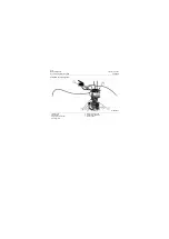
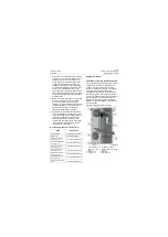
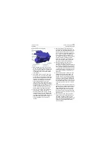
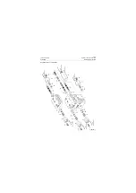
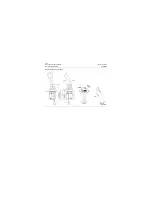
Exterior drawing of working pump
1. Load sensing port
2. Oil outlet
3. Housing return oil
4. Oil suction port
P18H00012
1
2
3
4
Summary of Contents for CLG835H
Page 2: ......
Page 4: ...Contents January 24 2017 CLG835H...
Page 6: ...1 2 General Information January 24 2017 CLG835H...
Page 38: ...1 34 Machine Inspection Table January 24 2017 CLG835H...
Page 156: ...3 2 Power Train System January 24 2017 CLG835H...
Page 214: ...3 2 Power Train System January 24 2017 CLG835H...
Page 272: ...3 60 Testing and adjustment January 24 2017 Power Train Test CLG835H...
Page 276: ...4 4 Hydraulic System January 24 2017 CLG835H...
Page 552: ...6 2 Driver s Cab System January 24 2017 CLG835H...
Page 608: ...7 2 Structure January 24 2017 CLG835H...
Page 662: ...8 4 Electrical System January 24 2017 CLG835H...
Page 677: ...8 19 January 24 2017 Structure Function Principle CLG835H Power System P18E00014...

