3-54
Removal and Installation
January 24, 2017
Removal and installation of rear axle assembly
CLG835H
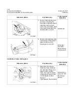
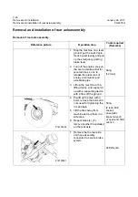
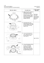
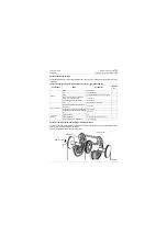
11. Horizontally place front
swing frame, and knock seal
ring into front swing frame
mounting hole to the end
with nylon hammer.
Caution: The seal ring lip
faces outward.
Nylon hammer
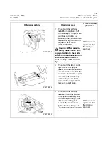
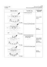
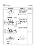
12. Press the bushing into the
front swing frame to the bot-
tom
Caution: The small hole
of bushing must toward
the lug end of front swing
support.
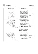
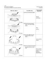
13. Install the snap ring into the
groove with straight screw-
driver.
Straight
screwdriver
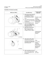
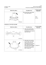
14. Knock seal ring into front
swing frame mounting slot to
the end with nylon hammer;
Caution:The seal ring lip
faces outward.
Reference picture
Operation step
Tools required
(Remarks)
Seal ring lip
P18T00114
Seal ring lip
P18T00115
P18T00116
Seal ring lip
P18T00117
Seal ring lip
Summary of Contents for CLG835H
Page 2: ......
Page 4: ...Contents January 24 2017 CLG835H...
Page 6: ...1 2 General Information January 24 2017 CLG835H...
Page 38: ...1 34 Machine Inspection Table January 24 2017 CLG835H...
Page 156: ...3 2 Power Train System January 24 2017 CLG835H...
Page 214: ...3 2 Power Train System January 24 2017 CLG835H...
Page 272: ...3 60 Testing and adjustment January 24 2017 Power Train Test CLG835H...
Page 276: ...4 4 Hydraulic System January 24 2017 CLG835H...
Page 552: ...6 2 Driver s Cab System January 24 2017 CLG835H...
Page 608: ...7 2 Structure January 24 2017 CLG835H...
Page 662: ...8 4 Electrical System January 24 2017 CLG835H...
Page 677: ...8 19 January 24 2017 Structure Function Principle CLG835H Power System P18E00014...

