4-58
Structure Function Principle
January 24, 2017
Brake system
CLG835H
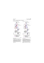
The priority valve 1 is used to supply oil for brake
system preferentially and unload after meeting
requirements for the accumulator of brake
system; the connecting/shut-off spool 3 is used
for setting the pressure for connecting and
shutting off charge valve; The shuttle valve 4 is
used to protect brake circuit A1 & A2 from
interference with each other.
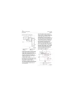
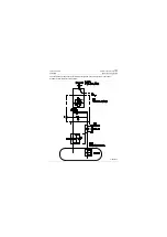
Hydraulic schematic of charge valve is shown in
the above Figure. P port is connected with pump,
A1 & A2 ports are connected with the
accumulator for service brake, B3 port is
connected with P port of brake valve block, and
then connected with parking brake accumulator,
T port is connected to oil tank and S port is
connected to oil tank.
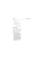
When the pressure of working oil port B3 of
charge valve is lower than connecting pressure
of charge valve (13.5±1MPa\1957.5±145psi), the
connecting/shut-off spool 3 works in upper
position and closes T port, the priority valve 1
works in right position; oil (via priority valve 1 and
check valve 2) from the pump is supplied for the
accumulator which reduces the pressure at B3
port. When the pressure of B3 port of charge
valve is higher than connecting pressure of
charge valve (16+0.5/-1 Mpa\2320+72.5/-
145psi), the connecting/shut-off spool 3 works in
lower position, oil from spring cavity of priority
valve 1 is connected with T port via connecting/
shut-off spool 3, the priority valve 1 works in left
position; all oil from the pump returns to oil tank
via S port. Recharge the accumulator as the
pressure of accumulator is lower than that of
connecting pressure of charge valve.
Hydraulic schematic of charge valve
1. Priority valve (main
spool)
2. Check valve
3. Connecting/shut-off
spool
4. Shuttle valve
P18H00045
1
2
3
4
Oil line diagram in charging state:
P18H00046
Summary of Contents for CLG835H
Page 2: ......
Page 4: ...Contents January 24 2017 CLG835H...
Page 6: ...1 2 General Information January 24 2017 CLG835H...
Page 38: ...1 34 Machine Inspection Table January 24 2017 CLG835H...
Page 156: ...3 2 Power Train System January 24 2017 CLG835H...
Page 214: ...3 2 Power Train System January 24 2017 CLG835H...
Page 272: ...3 60 Testing and adjustment January 24 2017 Power Train Test CLG835H...
Page 276: ...4 4 Hydraulic System January 24 2017 CLG835H...
Page 552: ...6 2 Driver s Cab System January 24 2017 CLG835H...
Page 608: ...7 2 Structure January 24 2017 CLG835H...
Page 662: ...8 4 Electrical System January 24 2017 CLG835H...
Page 677: ...8 19 January 24 2017 Structure Function Principle CLG835H Power System P18E00014...


