3-32
Removal and Installation
January 24, 2017
Removal and installation of torque converter-gearbox system
CLG835H
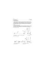
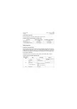
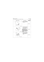
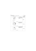
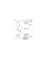
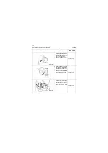
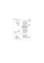
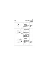
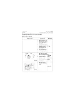
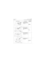
7. Screw and tighten the bolts
and washer for fastening the
gear box mount to the frame
with the torque of
2035±170Nm\
1500.8±125.38 lbf•ft.
46# wrench, 46#
socket,
pneumatic
impact wrench,
open-end 46#
fixed torque
spanner
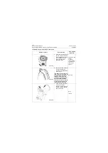
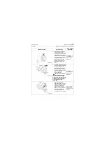
8. Attach the mounting end
flanges of drive shaft and
gear box to the rear output
flange of gear box, and
tighten the locknut to
132±10Nm\ 97.35±7.38
lbf•ft.
18# wrench or
open-end 18#
fixed torque
spanner
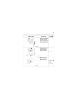
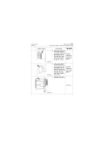
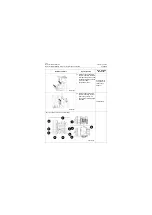
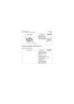
9. Attach the intermediate drive
shaft to front output flange of
gear box and tighten the
locknut to 200±15Nm\
147.5±11.06 lbf•ft.
21# wrench or
open-end 21#
fixed torque
spanner
Reference picture
Operation step
Tools required
(Remarks)
P18T00054
P18T00055
P18T00056
Summary of Contents for CLG835H
Page 2: ......
Page 4: ...Contents January 24 2017 CLG835H...
Page 6: ...1 2 General Information January 24 2017 CLG835H...
Page 38: ...1 34 Machine Inspection Table January 24 2017 CLG835H...
Page 156: ...3 2 Power Train System January 24 2017 CLG835H...
Page 214: ...3 2 Power Train System January 24 2017 CLG835H...
Page 272: ...3 60 Testing and adjustment January 24 2017 Power Train Test CLG835H...
Page 276: ...4 4 Hydraulic System January 24 2017 CLG835H...
Page 552: ...6 2 Driver s Cab System January 24 2017 CLG835H...
Page 608: ...7 2 Structure January 24 2017 CLG835H...
Page 662: ...8 4 Electrical System January 24 2017 CLG835H...
Page 677: ...8 19 January 24 2017 Structure Function Principle CLG835H Power System P18E00014...

