9-5
January 24, 2017
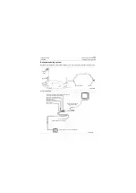
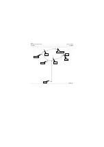
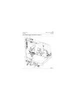
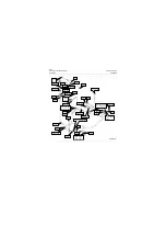
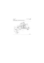
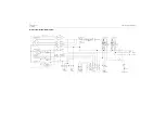
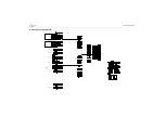
A/C System Schematic Diagram
CLG835H
A/C System Schematic Diagram
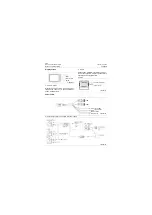
Control panel
Air speed switch gear 3
Mode switch
Cooling
Venting
Heating
Cooling adjust button
Outer circulation switch
Outer circulation lamp
Blue/black
Blue/black
Blue/yellow
Blue/yellow
Blue/white
Blue/
white
Yellow
Yellow
White
Red
Blue/white
White
Yellow
Black
Rheostat
Blower unit
Compressor relay
Earthing
Ignition signal
Compressor
Aluminum housing grounded
Pressure switch
Thermostat
Temperature
sensor
Air vent fan
Air vent fan
Green Green
Green
Control panel relay
Red
White
Red/blue
Red/blue
Black
Black
Heating lamp
Cooling lamp
White (gray)
White (gray)
Red/blue
Red/blue
Blue/black
Blue/
black
Blue/yellow
Blue/
yellow
Red/blue
Black
Green
Blue
Black
Red
Black
Black
White
White
White
White
Black
Black
gray
gray
Summary of Contents for CLG835H
Page 2: ......
Page 4: ...Contents January 24 2017 CLG835H...
Page 6: ...1 2 General Information January 24 2017 CLG835H...
Page 38: ...1 34 Machine Inspection Table January 24 2017 CLG835H...
Page 156: ...3 2 Power Train System January 24 2017 CLG835H...
Page 214: ...3 2 Power Train System January 24 2017 CLG835H...
Page 272: ...3 60 Testing and adjustment January 24 2017 Power Train Test CLG835H...
Page 276: ...4 4 Hydraulic System January 24 2017 CLG835H...
Page 552: ...6 2 Driver s Cab System January 24 2017 CLG835H...
Page 608: ...7 2 Structure January 24 2017 CLG835H...
Page 662: ...8 4 Electrical System January 24 2017 CLG835H...
Page 677: ...8 19 January 24 2017 Structure Function Principle CLG835H Power System P18E00014...

