8-88
Structure Function Principle
January 24, 2017
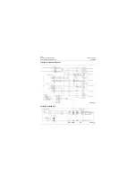
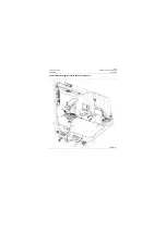
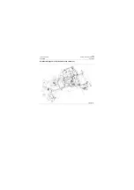
Backup monitoring system
CLG835H
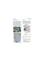
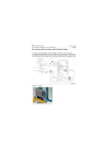
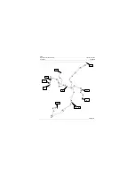
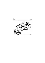
Display screen
1. Camera Option
When the monitoring system is active, whether
triggered, the camera 1 or 2 can be selected by
button "CAM SELECT".
2. Switch
Switch button "POWER" controls the on/off of
the monitoring system, while the switch button is
unavailable at the triggered state.
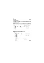
Power cable
P18E00156
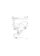
Menu
Camera option
Switch
Camera
P18E00157
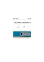
Audio receiver
Infrared LED display
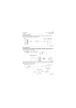
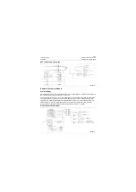
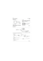
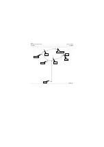
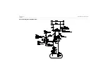
Circuit principle of the cab wire terminal power supply
P18E00158
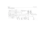
White Trigger CAM2
CAM2
Green Trigger CAM1
CAM1
DC 12/24 V
Red
Black Ground
P18E00159
Summary of Contents for CLG835H
Page 2: ......
Page 4: ...Contents January 24 2017 CLG835H...
Page 6: ...1 2 General Information January 24 2017 CLG835H...
Page 38: ...1 34 Machine Inspection Table January 24 2017 CLG835H...
Page 156: ...3 2 Power Train System January 24 2017 CLG835H...
Page 214: ...3 2 Power Train System January 24 2017 CLG835H...
Page 272: ...3 60 Testing and adjustment January 24 2017 Power Train Test CLG835H...
Page 276: ...4 4 Hydraulic System January 24 2017 CLG835H...
Page 552: ...6 2 Driver s Cab System January 24 2017 CLG835H...
Page 608: ...7 2 Structure January 24 2017 CLG835H...
Page 662: ...8 4 Electrical System January 24 2017 CLG835H...
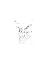
Page 677: ...8 19 January 24 2017 Structure Function Principle CLG835H Power System P18E00014...

