4-116
Removal and Installation
January 24, 2017
Work hydraulic system
CLG835H
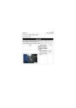
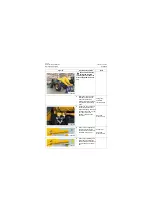
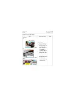
The boom shall be sup-
ported firmly before
removing the oil cylinder to
prevent the boom from fall-
ing.
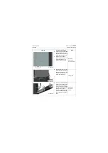
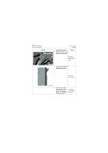
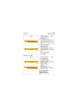
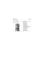
3. Sleeve the lifting rope con-
forming to safety require-
ments on the boom oil
cylinder and hang the boom
oil cylinder with a traveling
crane.
Lifting rope;
2T\4410lb
traveling crane
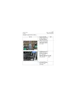
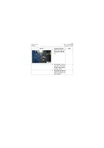
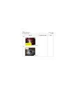
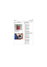
4. Loosen the hose plate bolt
connected with the steel
pipe below the big and small
cavities of the boom oil cylin-
der, remove the hose
assembly and mask the
hose joint.
Open-end
wrench: 13mm
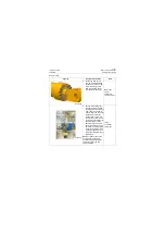
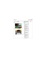
5. Remove the bolt tightening
the front pin shaft of the
boom and knock out the pin
shaft with a copper bar.
Copper bar;
Open-end
wrench: 27mm
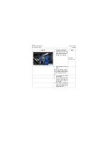
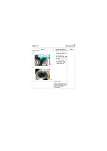
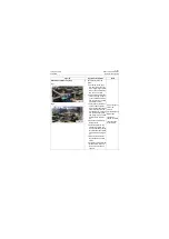
6. Remove the tightening bolt
of the rear pin shaft of the
boom cylinder and knock out
the pin shaft with a copper
bar.
Figures
Operation instruction
Tools
P18H00138
P18H00139
P18H00140
P18H00141
Summary of Contents for CLG835H
Page 2: ......
Page 4: ...Contents January 24 2017 CLG835H...
Page 6: ...1 2 General Information January 24 2017 CLG835H...
Page 38: ...1 34 Machine Inspection Table January 24 2017 CLG835H...
Page 156: ...3 2 Power Train System January 24 2017 CLG835H...
Page 214: ...3 2 Power Train System January 24 2017 CLG835H...
Page 272: ...3 60 Testing and adjustment January 24 2017 Power Train Test CLG835H...
Page 276: ...4 4 Hydraulic System January 24 2017 CLG835H...
Page 552: ...6 2 Driver s Cab System January 24 2017 CLG835H...
Page 608: ...7 2 Structure January 24 2017 CLG835H...
Page 662: ...8 4 Electrical System January 24 2017 CLG835H...
Page 677: ...8 19 January 24 2017 Structure Function Principle CLG835H Power System P18E00014...

