3-49
January 24, 2017
Removal and Installation
CLG835H
Removal and installation of rear axle assembly
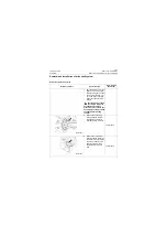
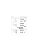
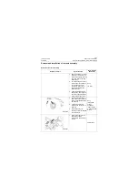
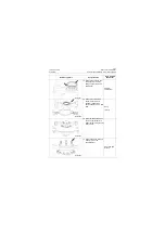
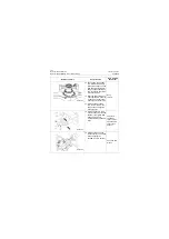
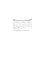
22. Remove the thrust washer.
Straight
screwdriver
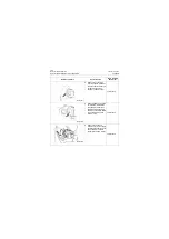
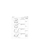
23. Remove the rear swing
support rack with a lifting
device.
Sling
(2 tons)
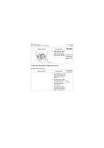
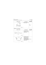
24. Screw the M8 bolt in the
dowel and remove the
dowel.
Open-end 13#
wrench
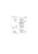
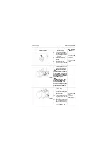
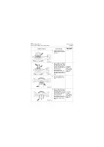
25. Remove the bolts and wash-
ers tightening the support
shaft.
Open-end 21#
wrench or 21#
socket,
pneumatic
impact wrench
Reference picture
Operation step
Tools required
(Remarks)
P18T00099
P18T00100
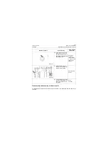
P18T00101
P18T00102
Summary of Contents for CLG835H
Page 2: ......
Page 4: ...Contents January 24 2017 CLG835H...
Page 6: ...1 2 General Information January 24 2017 CLG835H...
Page 38: ...1 34 Machine Inspection Table January 24 2017 CLG835H...
Page 156: ...3 2 Power Train System January 24 2017 CLG835H...
Page 214: ...3 2 Power Train System January 24 2017 CLG835H...
Page 272: ...3 60 Testing and adjustment January 24 2017 Power Train Test CLG835H...
Page 276: ...4 4 Hydraulic System January 24 2017 CLG835H...
Page 552: ...6 2 Driver s Cab System January 24 2017 CLG835H...
Page 608: ...7 2 Structure January 24 2017 CLG835H...
Page 662: ...8 4 Electrical System January 24 2017 CLG835H...
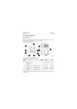
Page 677: ...8 19 January 24 2017 Structure Function Principle CLG835H Power System P18E00014...

