4-183
January 24, 2017
Removal and Installation
CLG835H
Steering hydraulic system
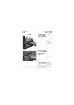
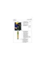
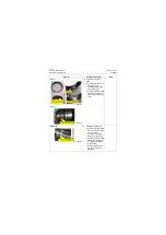
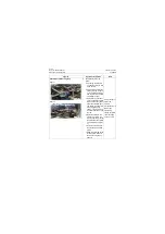
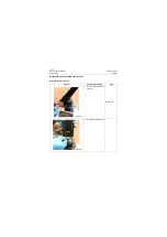
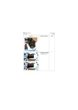
Assembly of cylinder head assembly:
Figure 1
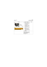
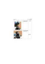
Figure 2
1. Assembly of cylinder head
assembly (assembly of
seal):
a. Clean the cylinder head,
and place it on the
assembly stand as shown
in figure 1 (dust ring side
faces upward).
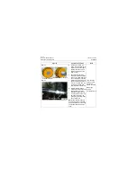
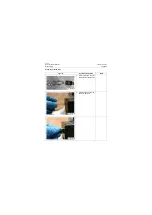
b. As shown in Figure 2,
assemble Y-ring into
green groove (shown in
Figure 1) with dual lip of
Y-ring facing downwards
(facing to the support
ring).
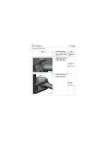
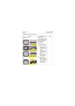
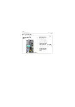
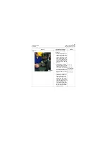
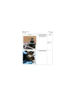
c. Assemble dust ring into
pink groove (shown in
Figure 1) with dual lip of
dust ring facing down-
wards (facing to the sup-
port ring) using the same
method of assembling Y-
ring.
d. Turn over the cylinder
head with the dust ring
facing downwards.
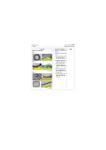
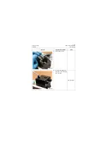
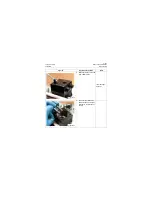
e. Press the supporting ring
(with opening) slightly by
hands and install it to the
red groove shown in fig-
ure 1.
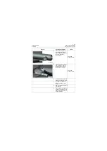
f. Install the O-ring of buffer
ring (formed by O-ring
and seal ring) to the blue
groove shown in figure 1
and then install the seal
ring to the outside of O-
ring.
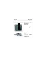
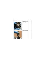
g. Assemble the O-ring into
its groove.
Assembling
tooling for dust
ring
Figures
Operation instruction
Tools
P18H00278
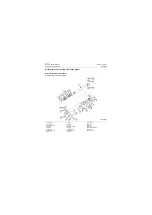
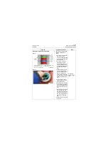
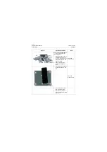
1. Pink: groove of dust ring
2. Green: groove of Y-ring
3. Red: groove of support ring
4. Blue: groove of buffer ring
5. Groove of O-ring
1
2
3
4
5
P18H00279
Summary of Contents for CLG835H
Page 2: ......
Page 4: ...Contents January 24 2017 CLG835H...
Page 6: ...1 2 General Information January 24 2017 CLG835H...
Page 38: ...1 34 Machine Inspection Table January 24 2017 CLG835H...
Page 156: ...3 2 Power Train System January 24 2017 CLG835H...
Page 214: ...3 2 Power Train System January 24 2017 CLG835H...
Page 272: ...3 60 Testing and adjustment January 24 2017 Power Train Test CLG835H...
Page 276: ...4 4 Hydraulic System January 24 2017 CLG835H...
Page 552: ...6 2 Driver s Cab System January 24 2017 CLG835H...
Page 608: ...7 2 Structure January 24 2017 CLG835H...
Page 662: ...8 4 Electrical System January 24 2017 CLG835H...
Page 677: ...8 19 January 24 2017 Structure Function Principle CLG835H Power System P18E00014...


