7-10
Removal and Installation
January 24, 2017
Removal and installation of hinge assembly
CLG835H
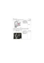
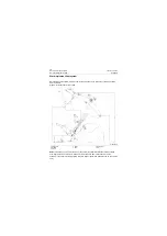
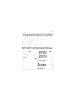
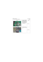
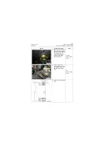
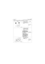
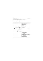
3. Install steering fixed link to
prevent front and rear
frames rotating.
Nipping pliers
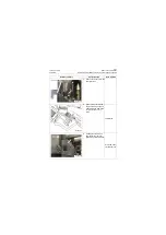
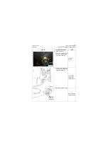
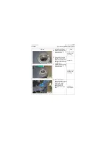
4. Remove upper hinge pin
1) Remove the upper hinge
captive bolt and take down
the cover plate
18# Wrench
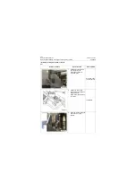
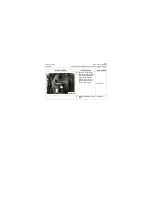
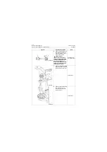
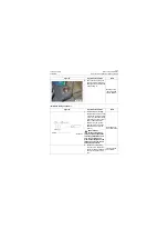
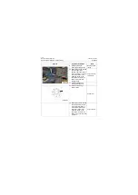
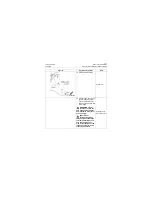
2) Knock out the upper hinge
pin with pin knocking tooling
and sledge hammer
Pin knocking
tooling and
sledge hammer
Figures
Operation instruction
Tools
P18S00007
P18S00008
P18S00009
Summary of Contents for CLG835H
Page 2: ......
Page 4: ...Contents January 24 2017 CLG835H...
Page 6: ...1 2 General Information January 24 2017 CLG835H...
Page 38: ...1 34 Machine Inspection Table January 24 2017 CLG835H...
Page 156: ...3 2 Power Train System January 24 2017 CLG835H...
Page 214: ...3 2 Power Train System January 24 2017 CLG835H...
Page 272: ...3 60 Testing and adjustment January 24 2017 Power Train Test CLG835H...
Page 276: ...4 4 Hydraulic System January 24 2017 CLG835H...
Page 552: ...6 2 Driver s Cab System January 24 2017 CLG835H...
Page 608: ...7 2 Structure January 24 2017 CLG835H...
Page 662: ...8 4 Electrical System January 24 2017 CLG835H...
Page 677: ...8 19 January 24 2017 Structure Function Principle CLG835H Power System P18E00014...

