5-20
Removal and Installation
January 24, 2017
Removal and installation of A/C components
CLG835H
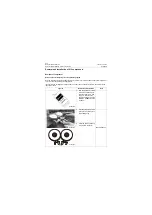
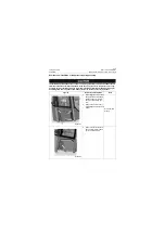
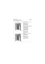
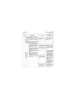
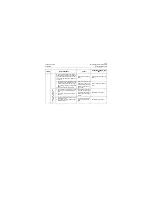
4. Remove the pipelines under
evaporator and mark that
with marker. Seal the con-
nectors with plastic bags
and adhesive tape after
removal, in order to prevent
foreign matter from entering
the line.
19#, 21#, 24#,
27# Open-end
wrenches
Plastic bags,
marker and
adhesive tape
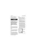
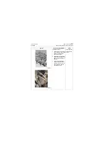
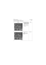
5. Open the cover plate of right
shutter inside cab.
Figures
Removal and installation
Tools
P18A00019
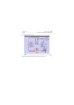
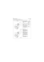
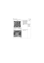
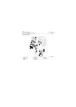
1. Water drain pipe
2. Warm water inlet pipeline
3. Warm water return pipeline
4. Water drain pipe
5. The hose from
evaporator to compressor
6. The hose from resevior
bottle to evaporator
2
3
4
5
6
1
P18A00020
Summary of Contents for CLG835H
Page 2: ......
Page 4: ...Contents January 24 2017 CLG835H...
Page 6: ...1 2 General Information January 24 2017 CLG835H...
Page 38: ...1 34 Machine Inspection Table January 24 2017 CLG835H...
Page 156: ...3 2 Power Train System January 24 2017 CLG835H...
Page 214: ...3 2 Power Train System January 24 2017 CLG835H...
Page 272: ...3 60 Testing and adjustment January 24 2017 Power Train Test CLG835H...
Page 276: ...4 4 Hydraulic System January 24 2017 CLG835H...
Page 552: ...6 2 Driver s Cab System January 24 2017 CLG835H...
Page 608: ...7 2 Structure January 24 2017 CLG835H...
Page 662: ...8 4 Electrical System January 24 2017 CLG835H...
Page 677: ...8 19 January 24 2017 Structure Function Principle CLG835H Power System P18E00014...

