5-26
Removal and Installation
January 24, 2017
Removal and installation of A/C components
CLG835H
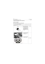
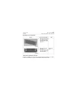
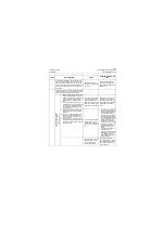
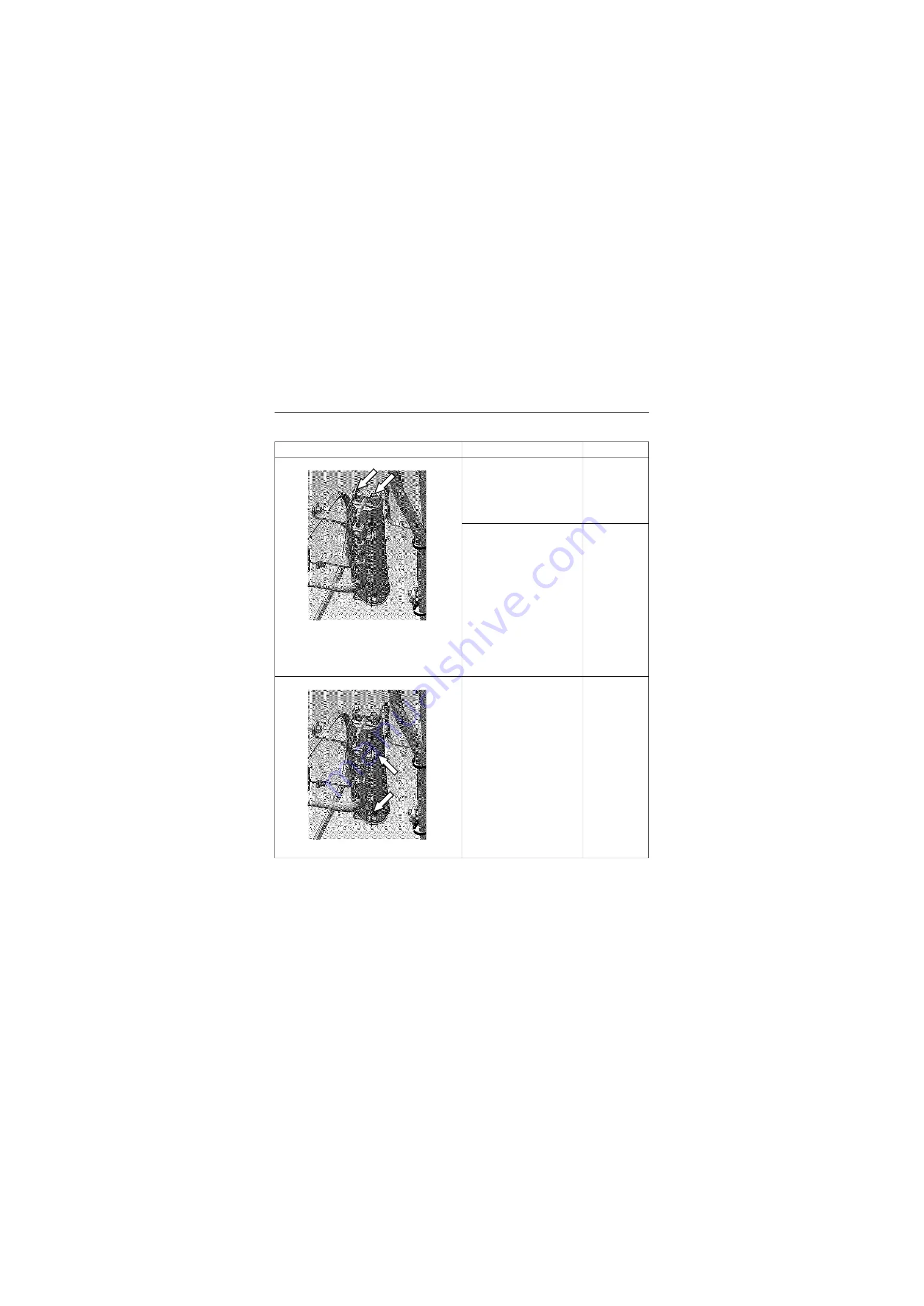
Removal and replacement of reservoir
Figures
Removal and installation
Tools
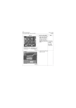
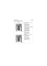
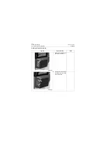
1. Open the cover
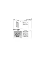
2. Drain refrigerant in air condi-
tioning system as required in
Release (recover) refriger-
ant in air conditioning sys-
tem.
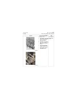
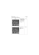
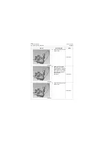
3. Remove the captive bolt of
the hose from condenser to
reservoir, and the captive
bolt of the hose from reser-
voir to evaporator. Remove
the hose from condenser to
reservoir, and the hose from
reservoir to evaporator. Seal
the open interfaces well with
plastic bags and adhesive
tapes.
4. Loosen the captive bolt on
the fluid receiver bracket
clamp. The refrigerant reser-
voir can be removed.
10# Wrench
Plastic bag, tape
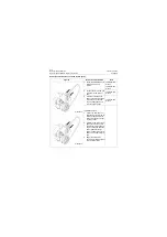
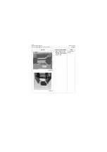
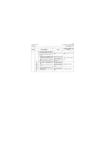
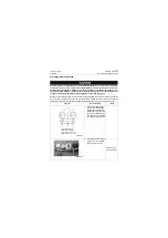
Installation method:
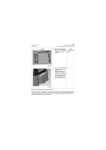
1. Place refrigerant reservoir in
the bracket, and tighten the
bolts on the bracket with
wrench.
2. Install the hose from con-
denser to reservoir and the
hose from reservoir to evap-
orator to the refrigerant res-
ervoir, and control the torque
to 4~7Nm.
10#Wrench
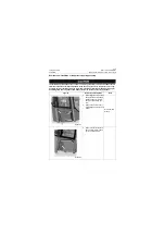
P18A00030
P18A00030
Summary of Contents for CLG835H
Page 2: ......
Page 4: ...Contents January 24 2017 CLG835H...
Page 6: ...1 2 General Information January 24 2017 CLG835H...
Page 38: ...1 34 Machine Inspection Table January 24 2017 CLG835H...
Page 156: ...3 2 Power Train System January 24 2017 CLG835H...
Page 214: ...3 2 Power Train System January 24 2017 CLG835H...
Page 272: ...3 60 Testing and adjustment January 24 2017 Power Train Test CLG835H...
Page 276: ...4 4 Hydraulic System January 24 2017 CLG835H...
Page 552: ...6 2 Driver s Cab System January 24 2017 CLG835H...
Page 608: ...7 2 Structure January 24 2017 CLG835H...
Page 662: ...8 4 Electrical System January 24 2017 CLG835H...
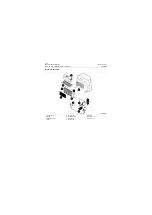
Page 677: ...8 19 January 24 2017 Structure Function Principle CLG835H Power System P18E00014...

