3-17
January 24, 2017
Structure Function Principle
CLG835H
Drive axle system
System schematic diagram and working
principle description
The drive axle for wheel loader is classified into
two classes, i.e. front axle and rear axle, the
main difference between which is the spiral
directions of the spiral bevel gear pairs in the
main drive. The driving spiral bevel gear of front
axle is left-handed, and that of rear axle is right-
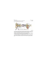
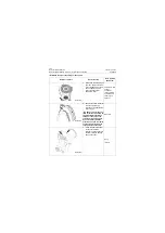
handed. The structure diagram for bevel gear
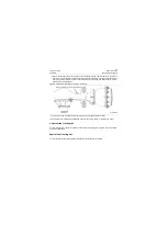
and wheel reducer of this machine is as shown in
figure 3-20 and 3-21.
The bevel gear structure is shown in Figure 3-21.
The bevel gear includes two parts, one is the
bevel gear composed of driving spiral bevel gear
and large size spiral bevel gear; the other is the
differential composed of cross axle and bevel
gear. The power is transmitted to the driving
spiral bevel gear by the gear box through drive
shaft, thus to drive the large size spiral bevel
gear with differential to rotate together. The half
shaft gear of differential passes the power to left/
right half shaft which is connected with the
splines, and further to the wheel reducer. The
power is then transmitted to hub and finally to
drive the tire to rotate after further speed
reduction, increasing torsion through wheel
reducer.
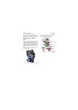
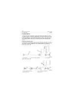
Figure 3-20 Structure diagram of the bevel gear
1. Driving spiral bevel gear
2. Axle housing
3. Driven spiral bevel gear
4. Carrier
5. Differential
P18T00020
1
2
3
4
5
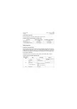
Figure 3-21 Diagram of the wheel reducer
1. Axle shaft
2. Planetary gear
3. Brake
4. Hub
5. Sun gear
P18T00021
1
2
3
4
5
Summary of Contents for CLG835H
Page 2: ......
Page 4: ...Contents January 24 2017 CLG835H...
Page 6: ...1 2 General Information January 24 2017 CLG835H...
Page 38: ...1 34 Machine Inspection Table January 24 2017 CLG835H...
Page 156: ...3 2 Power Train System January 24 2017 CLG835H...
Page 214: ...3 2 Power Train System January 24 2017 CLG835H...
Page 272: ...3 60 Testing and adjustment January 24 2017 Power Train Test CLG835H...
Page 276: ...4 4 Hydraulic System January 24 2017 CLG835H...
Page 552: ...6 2 Driver s Cab System January 24 2017 CLG835H...
Page 608: ...7 2 Structure January 24 2017 CLG835H...
Page 662: ...8 4 Electrical System January 24 2017 CLG835H...
Page 677: ...8 19 January 24 2017 Structure Function Principle CLG835H Power System P18E00014...


