8-18
Structure Function Principle
January 24, 2017
Power System
CLG835H
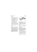
3. Connect the red probe of DMM to the positive
terminal of one battery, while the black probe
to the negative terminal of the other battery.
Be sure not to connect them to the cable ter-
minals. The value displayed on the DMM
shall be controlled within "24" to "32" V.
4. Keep the two pointers of the digital multime-
ter still. Put disconnect switch in the position
of "I". Switch on the electrical lock and start
the diesel engine.
5. The value displayed on the DMM is between
"20" to "24"V at the moment the cranking
motor starts running. The value returns to
that described in step 3 once the diesel
engine starts smoothly.
Any battery that is capable of completing the
above steps and successfully starting the diesel
engine, is in good service condition; otherwise,
test by following steps.
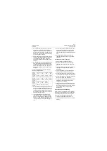
1. Disconnect all the battery connecting cables,
thereby, two batteries are completely discon-
nected.
2. Turn the digital multimeter to 50 V of voltage
position.
3. Connect the red probe of DMM to the positive
terminal of one battery, while the black probe
to the negative terminal, the value displayed
on the DMM is around "12" to "16" V.
4. Inspect the other battery according to step3.
The displayed value is the same as the step
3. Any battery that fails to implement the test
procedures, shall be charged or replaced.
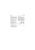
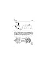
Power supply relay
The machine is equipped with a relay for power
control, besides, other than normally closed
contacts, a group of normally open contacts is
also provided. Both the relay parameters and
internal schematics are labeled on the relay
housing. The rated current of normally open
contacts on the relay contact circuit is 100A.
Apply +24 V voltage to the relay coil, then the
electromagnetic force generated by the
energized attracts the armature inside the relay,
whereby, the normally open contracts switch on.
The relay is assembled around the centralized
control box of electric appliance.
Precautions
+A1 indicates the current input direction, and -A2
shows the current output direction. In the case of
connection error, the inoperative magnetic
blowout function of contactor will shorten its
service life.
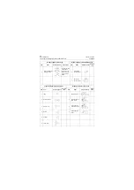
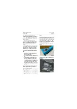
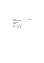
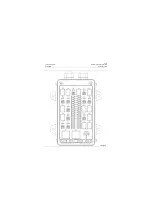
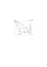
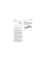
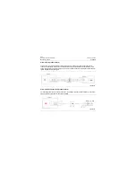
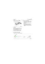
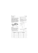
Socket relay is concentrated on the control box,
of which the location schematic and function
diagram are as shown below. The location and
function definitions of socket relay will not appear
hereinafter.
P18E00012
P18E00013
Summary of Contents for CLG835H
Page 2: ......
Page 4: ...Contents January 24 2017 CLG835H...
Page 6: ...1 2 General Information January 24 2017 CLG835H...
Page 38: ...1 34 Machine Inspection Table January 24 2017 CLG835H...
Page 156: ...3 2 Power Train System January 24 2017 CLG835H...
Page 214: ...3 2 Power Train System January 24 2017 CLG835H...
Page 272: ...3 60 Testing and adjustment January 24 2017 Power Train Test CLG835H...
Page 276: ...4 4 Hydraulic System January 24 2017 CLG835H...
Page 552: ...6 2 Driver s Cab System January 24 2017 CLG835H...
Page 608: ...7 2 Structure January 24 2017 CLG835H...
Page 662: ...8 4 Electrical System January 24 2017 CLG835H...
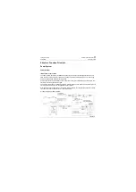
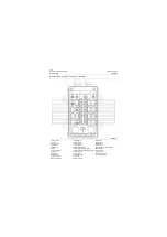
Page 677: ...8 19 January 24 2017 Structure Function Principle CLG835H Power System P18E00014...


