3-25
January 24, 2017
Removal and Installation
CLG835H
Removal and installation of torque converter-gearbox system
Removal and Installation
Removal and installation of torque converter-gearbox system
Removal of torque converter - gearbox system
Reference picture
Operation step
Tools required
(Remarks)
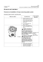
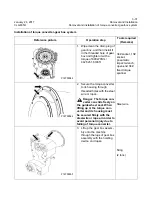
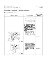
1. Stop the machine on a level
ground, put the work imple-
ment, bucket levelly, and pull
up the emergency parking
brake lever.
2. Turn off the engine and
remove the key.
3. Remove the drain plug of
gear box assembly to drain
the oil.
Caution: The waste oil
shall be recovered in a
container during removal, in
order to avoid environmental
contamination. The removed
hose is shielded to avoid con-
tamination of parts.
Danger: It is sure that the
hose pressure is fully
discharged and the oil is
cooled sufficiently before
removal of hose, in order to
avoid personal injury of hose
pressure and hot oil during
removal.
34# socket, 13#
socket,
pneumatic
impact wrench
4. Remove the cab assembly
of machine, see section
“Removal and Installation of
Cab” for removal steps.
P18T00032
Summary of Contents for CLG835H
Page 2: ......
Page 4: ...Contents January 24 2017 CLG835H...
Page 6: ...1 2 General Information January 24 2017 CLG835H...
Page 38: ...1 34 Machine Inspection Table January 24 2017 CLG835H...
Page 156: ...3 2 Power Train System January 24 2017 CLG835H...
Page 214: ...3 2 Power Train System January 24 2017 CLG835H...
Page 272: ...3 60 Testing and adjustment January 24 2017 Power Train Test CLG835H...
Page 276: ...4 4 Hydraulic System January 24 2017 CLG835H...
Page 552: ...6 2 Driver s Cab System January 24 2017 CLG835H...
Page 608: ...7 2 Structure January 24 2017 CLG835H...
Page 662: ...8 4 Electrical System January 24 2017 CLG835H...
Page 677: ...8 19 January 24 2017 Structure Function Principle CLG835H Power System P18E00014...

