4-149
January 24, 2017
Removal and Installation
CLG835H
Work hydraulic system
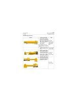
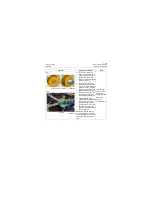
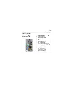
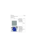
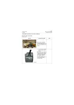
Fig. I
4. Assembly of oil cylinder
assembly:
a. Fix the cylinder block on
the assembly stand (fig-
ure 1) to make it not
rotate, apply clean
hydraulic oil to the inner
chamber of cylinder block
about 300mm\11.8in from
top to bottom.
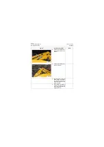
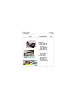
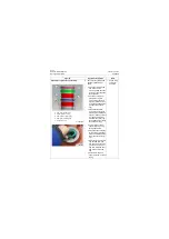
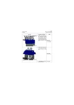
b. Lift the piston rod group
with sling and apply clean
hydraulic oil to the excir-
cle of piston, then install it
to the cylinder block verti-
cally along with the axis of
inner chamber of cylinder
block.
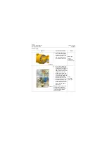
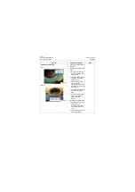
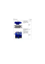
c. Screw 12 M16×70-10.9-
Zn.D screws to the
threaded hole (screwed
for at least 5 threads) by
hands, then tighten the
screws to the range
267±45Nm\196.9±33.2lbf·
ft one by one diagonally
with blower gun.
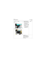
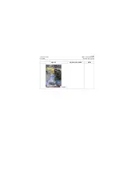
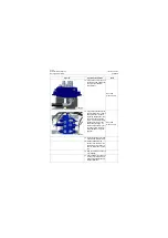
d. Seal the big and small
cavity of oil port with spe-
cial cap.
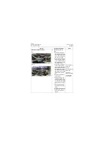
Lifting rig
Lifting rope
Blower gun
Figures
Operation instruction
Tools
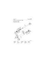
P18H00210
Summary of Contents for CLG835H
Page 2: ......
Page 4: ...Contents January 24 2017 CLG835H...
Page 6: ...1 2 General Information January 24 2017 CLG835H...
Page 38: ...1 34 Machine Inspection Table January 24 2017 CLG835H...
Page 156: ...3 2 Power Train System January 24 2017 CLG835H...
Page 214: ...3 2 Power Train System January 24 2017 CLG835H...
Page 272: ...3 60 Testing and adjustment January 24 2017 Power Train Test CLG835H...
Page 276: ...4 4 Hydraulic System January 24 2017 CLG835H...
Page 552: ...6 2 Driver s Cab System January 24 2017 CLG835H...
Page 608: ...7 2 Structure January 24 2017 CLG835H...
Page 662: ...8 4 Electrical System January 24 2017 CLG835H...
Page 677: ...8 19 January 24 2017 Structure Function Principle CLG835H Power System P18E00014...

