4-171
January 24, 2017
Removal and Installation
CLG835H
Steering hydraulic system
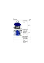
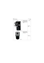
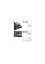
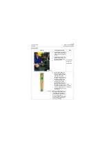
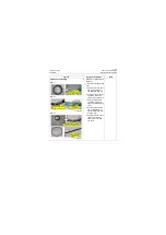
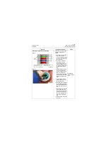
3. Remove the tightening bolt
of rear pin shaft of steering
cylinder and knock out the
pin shaft by copper bar;
Copper bar;
Open-end
wrench: 15mm
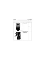
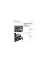
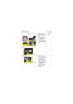
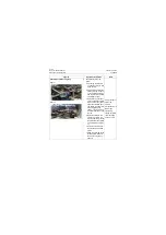
4. Tie the steering cylinder with
lifting rope, remove the tight-
ening bolt of front pin shaft
of steering cylinder and
knock the pin shaft out with
copper bar.
Copper bar;
Open-end
wrench: 15mm
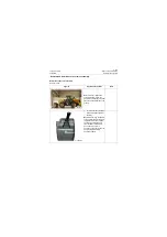
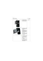
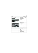
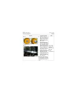
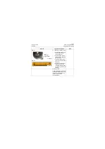
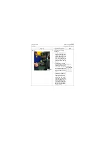
5. Lift the steering cylinder out
of the frame using traveling
crane and place it on a level
ground.
Lifting rope;
2t\4410lb
traveling crane
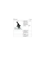
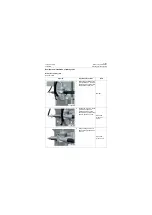
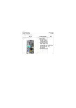
6. Mask the big and small cav-
ity oil ports of the steering
cylinder to avoid pollution.
Shielding film
Figures
Operation instruction
Tools
P18H00255
P18H00256
Summary of Contents for CLG835H
Page 2: ......
Page 4: ...Contents January 24 2017 CLG835H...
Page 6: ...1 2 General Information January 24 2017 CLG835H...
Page 38: ...1 34 Machine Inspection Table January 24 2017 CLG835H...
Page 156: ...3 2 Power Train System January 24 2017 CLG835H...
Page 214: ...3 2 Power Train System January 24 2017 CLG835H...
Page 272: ...3 60 Testing and adjustment January 24 2017 Power Train Test CLG835H...
Page 276: ...4 4 Hydraulic System January 24 2017 CLG835H...
Page 552: ...6 2 Driver s Cab System January 24 2017 CLG835H...
Page 608: ...7 2 Structure January 24 2017 CLG835H...
Page 662: ...8 4 Electrical System January 24 2017 CLG835H...
Page 677: ...8 19 January 24 2017 Structure Function Principle CLG835H Power System P18E00014...


