4-219
January 24, 2017
Removal and Installation
CLG835H
Brake system
Removal and installation of accumulator
Removal steps:
Assembly steps: assemble it in the reverse order of the removal steps.
Refer to Pressure Release of Hydraulic system to release the pressure of service brake system
and parking brake system before removing the accumulator.
Figures
Operation instruction
Tools
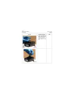
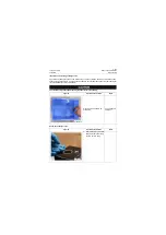
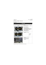
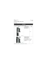
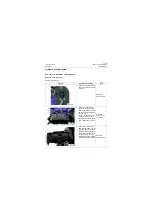
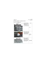
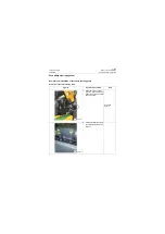
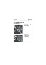
Open door of left housing:
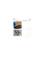
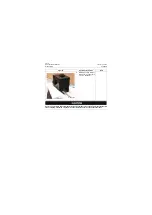
1. Mark accumulators respec-
tively as BR1, BR2 and BR3
and hoses connecting with
their lower parts as A1, A2
and B3, note that markings
shall be firm; remove hoses
and joints under accumula-
tors and mask oil ports;
Open-end
wrench: 10mm,
22mm and
24mm;
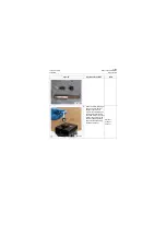
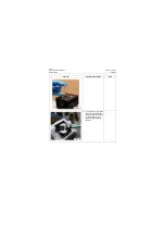
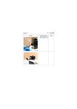
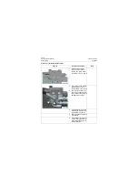
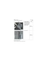
2. Remove the 6 bolts from the
accumulator;
Open-end
wrench:
10mm
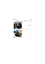
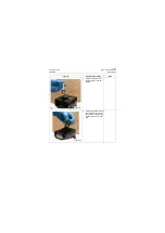
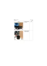
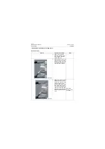
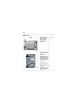
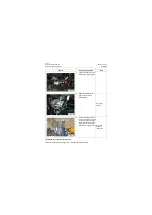
3. Take the accumulator out of
left housing;
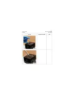
4. Shield the joint of accumula-
tor and store it in dry and
clean place.
P18H00348
P18H00349
P18H00350
Summary of Contents for CLG835H
Page 2: ......
Page 4: ...Contents January 24 2017 CLG835H...
Page 6: ...1 2 General Information January 24 2017 CLG835H...
Page 38: ...1 34 Machine Inspection Table January 24 2017 CLG835H...
Page 156: ...3 2 Power Train System January 24 2017 CLG835H...
Page 214: ...3 2 Power Train System January 24 2017 CLG835H...
Page 272: ...3 60 Testing and adjustment January 24 2017 Power Train Test CLG835H...
Page 276: ...4 4 Hydraulic System January 24 2017 CLG835H...
Page 552: ...6 2 Driver s Cab System January 24 2017 CLG835H...
Page 608: ...7 2 Structure January 24 2017 CLG835H...
Page 662: ...8 4 Electrical System January 24 2017 CLG835H...
Page 677: ...8 19 January 24 2017 Structure Function Principle CLG835H Power System P18E00014...


