4-185
January 24, 2017
Removal and Installation
CLG835H
Steering hydraulic system
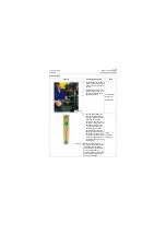
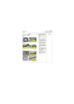
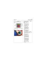
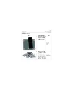
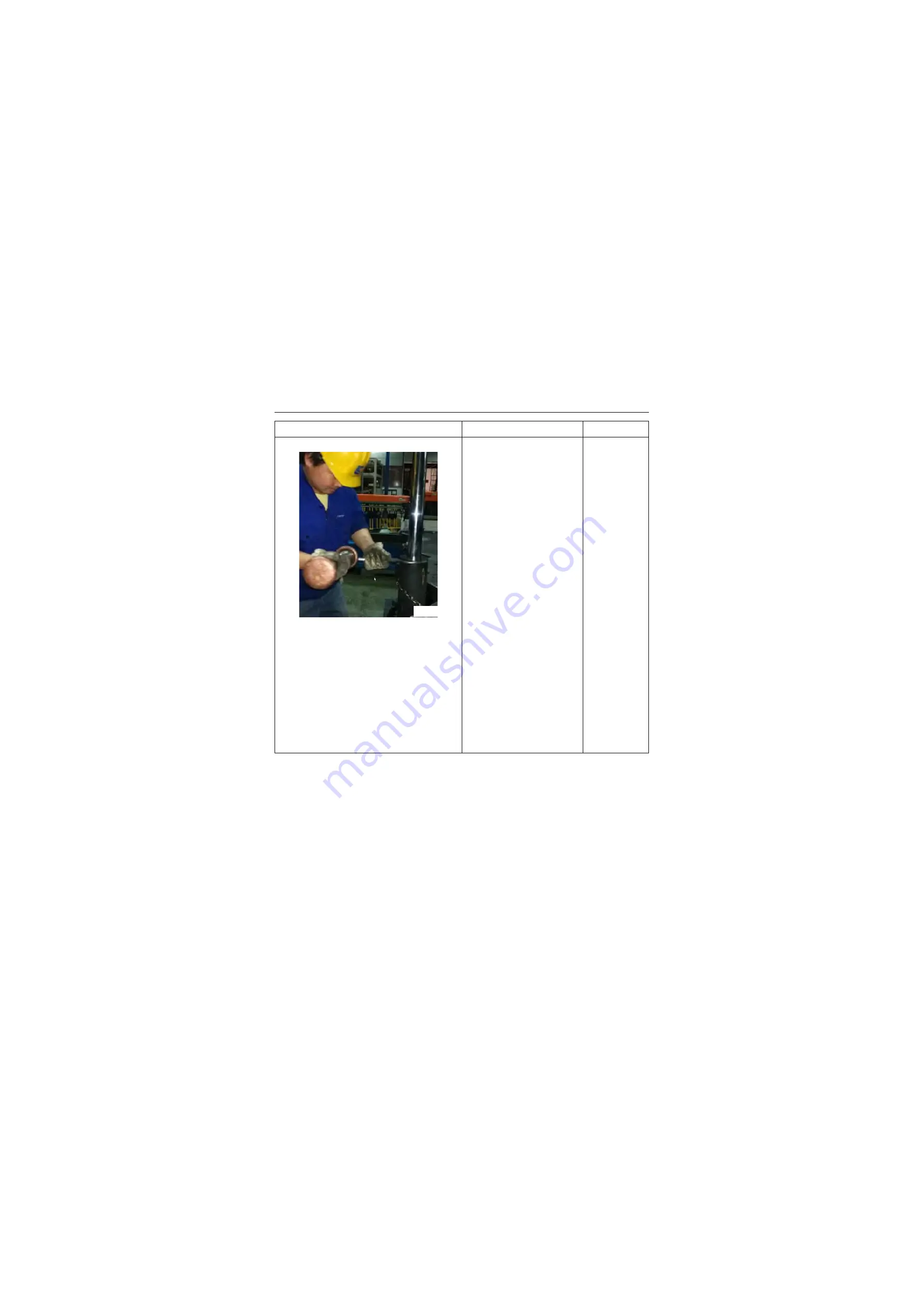
Figure 1
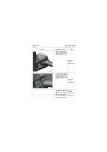
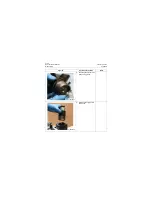
3. Assembly of oil cylinder
assembly:
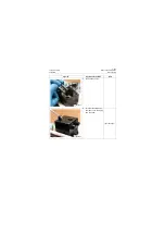
a. Fix the cylinder block on
assembly stand so that it
can not turn (As shown in
Figure I and Figure II) and
apply cleaning hydraulic
oil on inner cavity of cylin-
der block within the area
of 300mm\ 11.8in from up
to down.
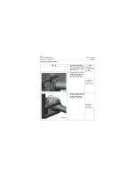
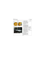
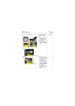
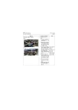
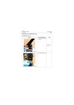
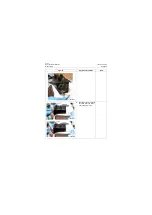
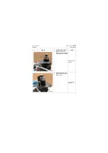
b. Lift the piston rod group
with sling and apply clean
hydraulic oil to the excir-
cle of piston, then install it
to the cylinder block verti-
cally along with the axis of
inner chamber of cylinder
block.
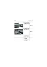
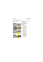
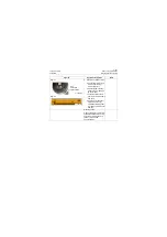
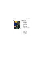
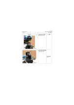
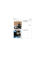
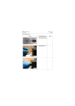
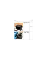
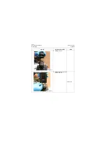
c. Tighten the cylinder head
clockwise using hook
spanner and knock the
hook spanner with cop-
per bar, and then install
boosting rod on the hook
spanner to tighten the cyl-
inder continuously (Fig-
ure II) to make tightening
torque of cylinder head
thread reach 332±20Nm\
244.9±14.8lbf·ft.
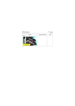
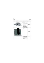
Lifting rig
Lifting rope
Hook spanner
Copper bar
Boosting rod
Figures
Operation instruction
Tools
P18H00282
Summary of Contents for CLG835H
Page 2: ......
Page 4: ...Contents January 24 2017 CLG835H...
Page 6: ...1 2 General Information January 24 2017 CLG835H...
Page 38: ...1 34 Machine Inspection Table January 24 2017 CLG835H...
Page 156: ...3 2 Power Train System January 24 2017 CLG835H...
Page 214: ...3 2 Power Train System January 24 2017 CLG835H...
Page 272: ...3 60 Testing and adjustment January 24 2017 Power Train Test CLG835H...
Page 276: ...4 4 Hydraulic System January 24 2017 CLG835H...
Page 552: ...6 2 Driver s Cab System January 24 2017 CLG835H...
Page 608: ...7 2 Structure January 24 2017 CLG835H...
Page 662: ...8 4 Electrical System January 24 2017 CLG835H...
Page 677: ...8 19 January 24 2017 Structure Function Principle CLG835H Power System P18E00014...

